Views: 0 Author: LIB Team Publish Time: 2026-09-23 Origin: Site


Have you ever pulled a batch of components from a chamber after a 500-hour cycle, only to realize the data is unusable? In corrosion testing, incorrect sample setup can compromise an otherwise carefully controlled evaluation.
Modern environmental testing equipment provides precise temperature, humidity, and atomization control, but specimen preparation and positioning remain essential to test validity. This guide explains the practical placement rules, mounting methods, and preparation steps required for repeatable salt spray corrosion testing.
For laboratories performing ASTM B117 and related corrosion evaluations, LIB Industry provides salt spray test chambers designed to maintain stable environmental conditions while supporting flexible specimen placement.
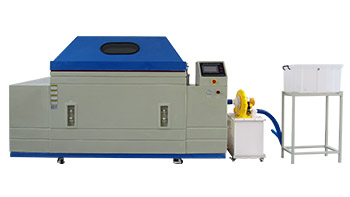
A customer from Pakistan shared feedback after using the LIB S-150 Salt Spray Test Chamber: “Machine is working in good condition and there is no problem.” This practical feedback reflects the reliable operation and stable performance of LIB corrosion testing equipment in real-world applications.
Inquire About Salt Spray Test Chamber
Optimal Orientation: Specimens should typically be positioned at a 15 to 30-degree angle from the vertical to support uniform mist settling and controlled runoff.
Zero Interference: Test specimens should not touch each other or the chamber walls.
Drip Prevention: Samples must be positioned so condensation or corrosion products from upper specimens do not drip onto lower ones.
Inert Fixtures: Non-reactive mounting materials such as PVC, acrylic, Teflon, or FRP help prevent galvanic interference.
Strict Compliance: Consistent positioning is essential for repeatable ASTM B117 and similar corrosion test results.
Material durability testing requires high repeatability. Automotive, aerospace, electronics, coating, and metal-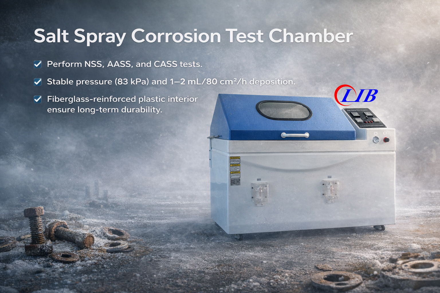 processing industries increasingly rely on accelerated corrosion tests to validate new materials, coatings, and surface treatments. As test equipment becomes more automated, specimen positioning remains one of the most important manual variables.
Incorrect orientation can alter:
① Salt fog exposure
② Moisture accumulation
③ Runoff behavior
④ Corrosion rate
⑤ Comparison between batches
Standardized loading procedures therefore play an important role in maintaining reliable long-term test data.
A salt spray corrosion test chamber is designed to expose specimens to a uniform corrosive environment.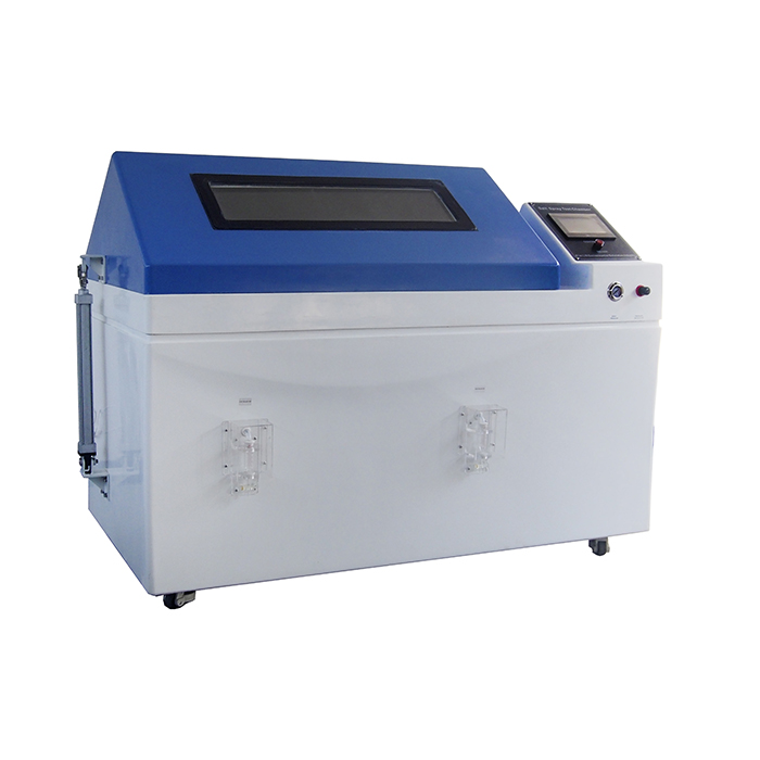
If physical positioning disrupts that environment, the resulting corrosion performance may no longer represent the intended test conditions.
Salt fog must circulate freely around each test specimen.
When the chamber atomizes a 5% sodium chloride solution, fine droplets should settle evenly across exposed surfaces.
Poor positioning can create shielding.
For example, a large automotive component positioned directly in front of a smaller fastener may block part of the salt fog distribution.
The shielded sample then receives less chloride exposure, producing artificially favorable results.
For this reason, laboratories should maintain clear spacing between specimens and avoid blocking the primary fog circulation path.
Corrosion testing is only useful when results can be reproduced.
Specimen angle directly affects moisture accumulation and liquid runoff.
If the same coated panel is tested at different angles in separate batches, corrosion rates may differ even when the material is identical.
A consistent positioning method helps eliminate this variable and improves comparison between:
Different production batches
Different coating suppliers
Different laboratories
Different test periods
A correct ASTM B117 test setup requires controlled specimen placement. Although exact requirements depend on the applicable standard and specimen geometry, several general principles are commonly followed.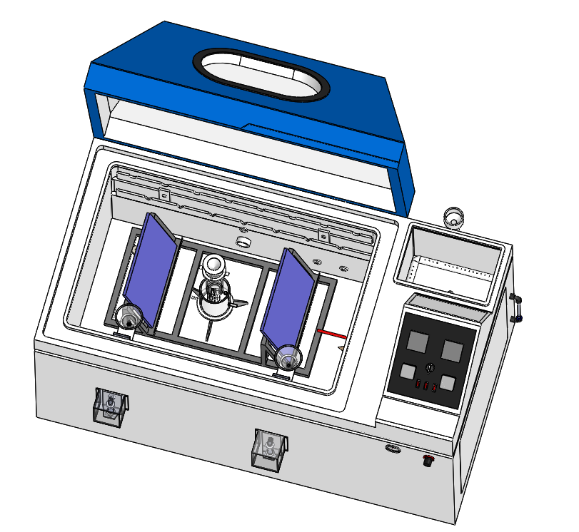
Flat test panels are generally positioned between 15 and 30 degrees from vertical.
This test sample angle allows fine saline droplets to settle on the exposed surface while enabling condensed liquid to drain naturally.
If the panel is positioned too flat, salt solution can pool on the surface.
This may create an artificially aggressive immersion-like condition.
If the specimen is too vertical, salt fog may not settle on the test surface as effectively.
Maintaining a consistent test angle therefore improves repeatability.
Adequate clearance helps maintain uniform airflow and fog circulation.
Useful placement guidelines include:
Distance from Walls: Keep specimens away from chamber walls to reduce the risk of wall condensation dripping onto samples.
Distance Between Samples: Maintain enough clearance so adjacent specimens do not shield one another.
Distance from Chamber Floor: Keep samples above pooled runoff or drainage areas.
Exact clearances should follow the chamber design and applicable test standard.
Flat panels are relatively simple to position, but real components often include irregular shapes, fasteners, brackets, housings, and assemblies. Regardless of geometry, operators should control runoff, spacing, and direct fog exposure.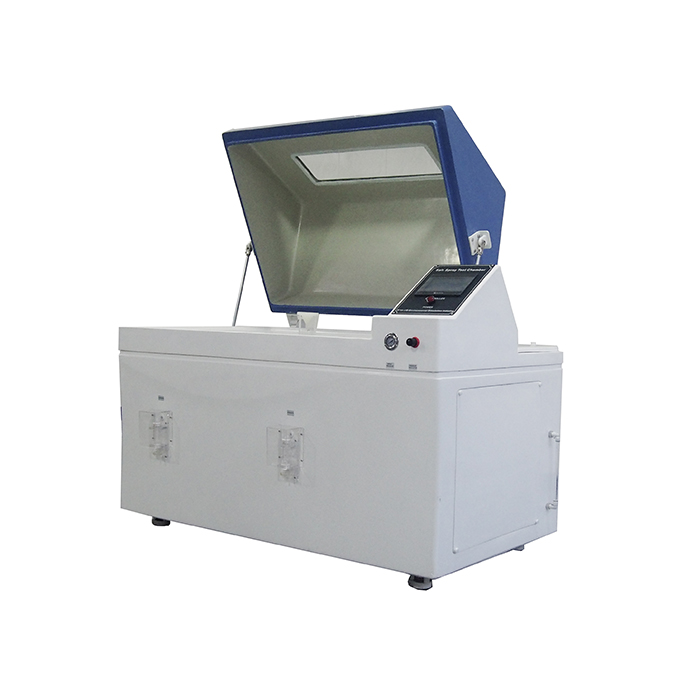
One major positioning error occurs when condensation or corrosion products from one specimen drip onto another.
As salt fog reacts with metal surfaces, runoff can contain:
① Zinc corrosion products
② Iron corrosion products
③ Dissolved salts
④ Altered pH
If an upper specimen drips onto a lower specimen, the lower sample is exposed to a different chemical environment.
This can accelerate corrosion artificially.
Specimens of the Salt Spray Corrosion Test Chamber should therefore be staggered or positioned so runoff falls directly toward the chamber collection area rather than onto another sample.
Test samples of the should not touch each other.
Physical contact can create:
① Moisture traps
② Crevice corrosion
③ Galvanic interaction
④ Localized shielding
This is particularly important when testing different metals. Large components should also be positioned carefully so they do not block smaller samples from receiving salt fog.
The specimen holder is exposed to the same corrosive environment as the test pieces. Its material should therefore be chemically stable and non-reactive.
A suitable salt spray specimen holder may be manufactured from materials such as:
PVC
Acrylic
Teflon
Rubber
Glass
FRP
Metallic racks can introduce unwanted galvanic interactions if they contact the test specimen. In a saline environment, direct contact between different metals can create an electrochemical cell and alter the natural corrosion behavior of the specimen. For this reason, LIB Industry salt spray test chambers use corrosion-resistant internal structures and support racks suitable for demanding saline environments.
Different sample geometries require different mounting methods.
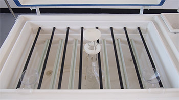
① V-Groove Racks: Suitable for flat panels because they support a consistent test angle while minimizing contact with the exposed surface.
② Hanging Rods: Useful for fasteners, springs, brackets, and irregular components that require broader surface exposure.
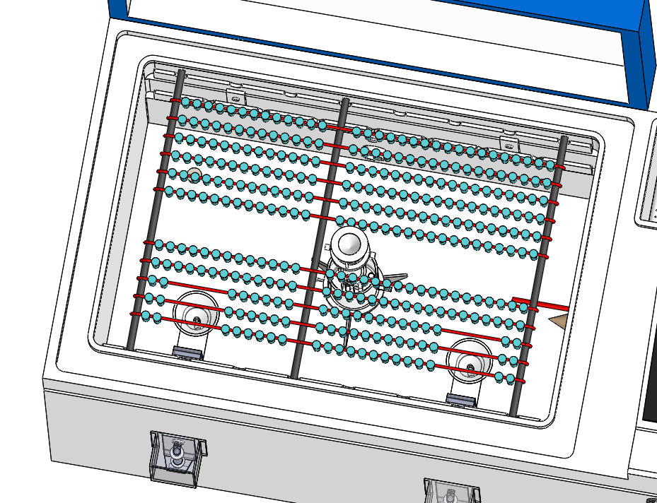
When suspending components, nylon threads, Teflon hooks, or other non-reactive materials should be used.
Correct positioning cannot compensate for poor sample preparation.
Fingerprints, oils, machining fluids, and surface contamination can affect corrosion behavior.
Before testing, specimens should be cleaned according to the applicable procedure.
Possible contaminants include:
Machining oils
Protective shipping oils
Dust
Metal debris
Fingerprints
Suitable solvents or cleaning methods should remove these contaminants without attacking the protective coating being tested.
After cleaning, specimens should be handled with clean gloves to avoid recontamination.
When evaluating coated panels, cut edges may expose bare metal that is not part of the coating system being tested.
These edges can corrode rapidly and may influence the main test surface.
Depending on the test method, cut edges may need to be protected using:
Inert wax
Chemical-resistant tape
Protective paint
Identification marks should also be placed on non-critical areas.
Not every specimen can follow the same placement rule. Finished components may have irregular shapes, recessed surfaces, multiple angles, and complex geometries.
Zinc-plated or galvanized components produce white corrosion products during exposure. If the geometry allows liquid and zinc corrosion products to accumulate in deep recesses, moisture may remain trapped. This can accelerate localized degradation. Operators should therefore position zinc-coated parts so liquid can drain naturally whenever possible.
For irregular components, laboratories should identify the significant surface. This is the area most important to the product's function or expected service exposure. The significant surface should receive unobstructed salt fog. For highly asymmetrical products, multiple identical components may be tested at different orientations so several critical surfaces can be evaluated.
| LIB Popular Environmental Chamber | |||
 |  |
| 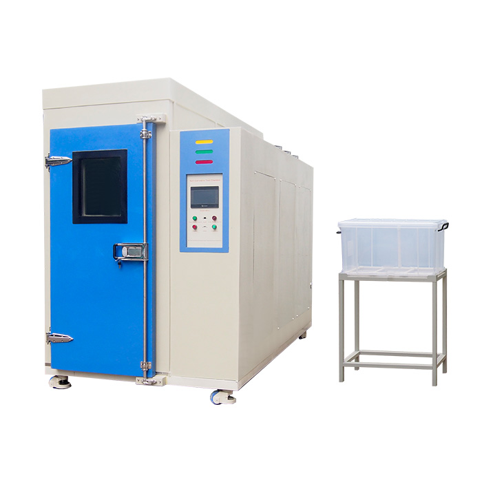 |
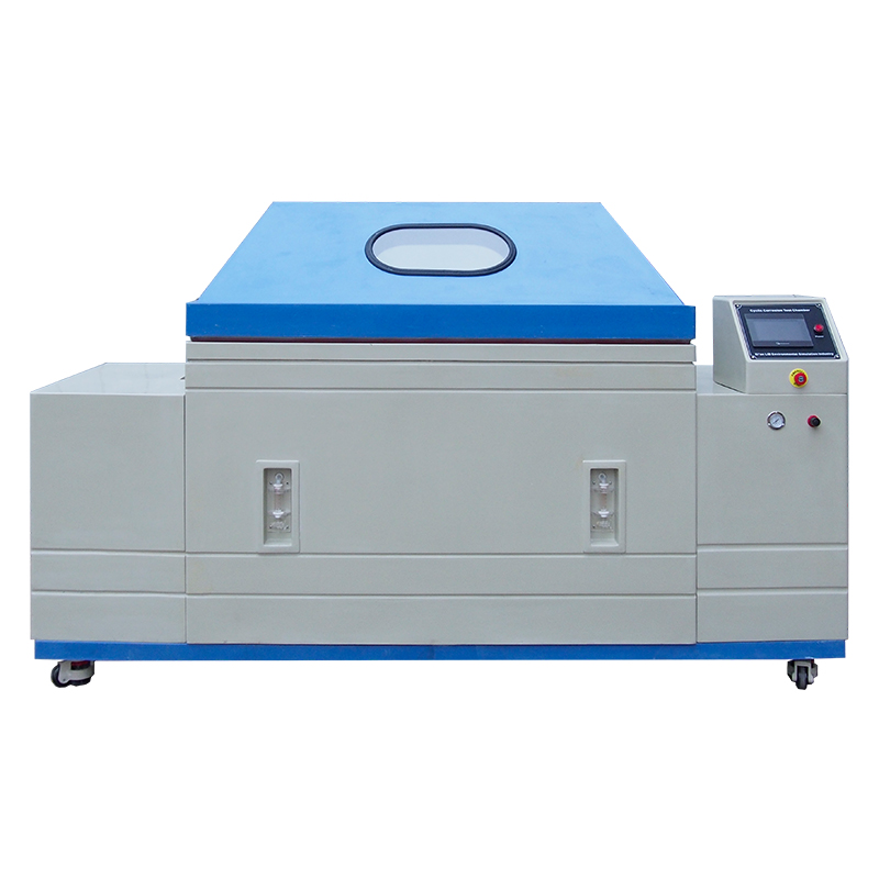
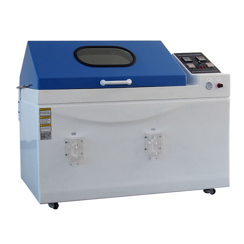
Cyclic Salt Spray Corrosion Chamber Realistic Wet-Dry Corrosion Simulation, Accelerated Corrosion Testing for Long-Term Durability | ASTM B117 Basic Fog Corrosion Salt Spray Test Cabinet Reliable Salt Fog Exposure Testing, Accurate Corrosion Resistance Evaluation | Salt Spray and Sulfur Dioxide Climatic Chamber Simulate Acid Rain and Industrial Pollution, Advanced SO₂ Corrosion Testing Solution | Walk-in Salt Spray Corrosion Chamber Large-Capacity Corrosion Testing Space, Ideal for Oversized Components and Assemblies |
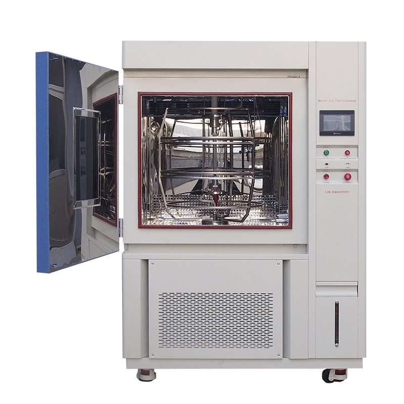 | 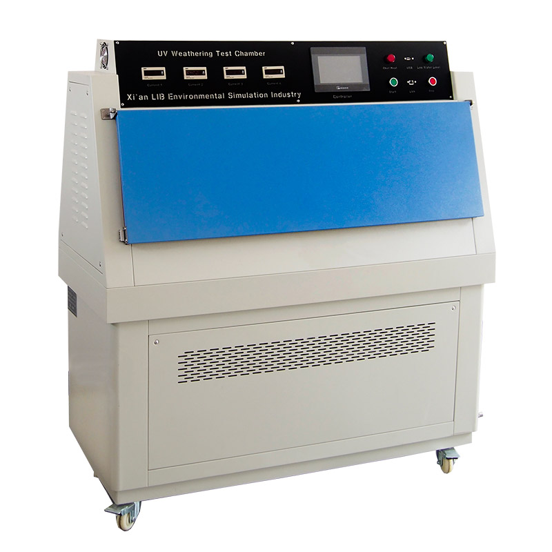 | 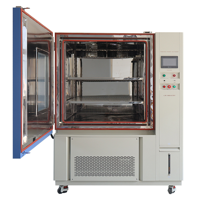 | 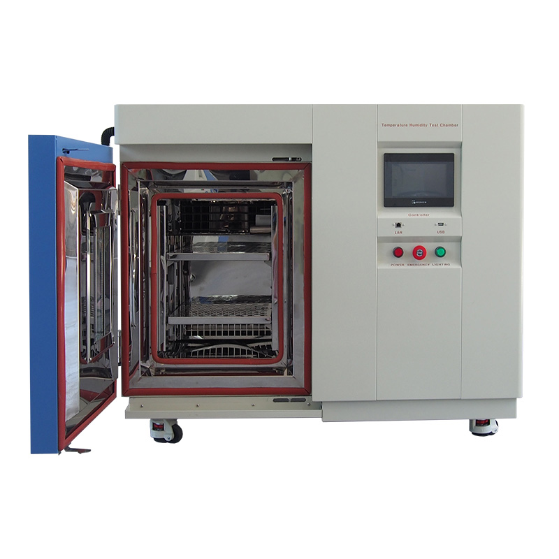 |
ASTM G155 G151 Accelerated Weathering XenonTest Apparatus Full-Spectrum Sunlight Simulation, Accelerated Outdoor Weathering Analysis | UVA 340 Fluorescent Lamp Light Fastness Test Instrument Precise UV Aging Performance Testing, Reliable Material Durability Verification | Temperature Humidity Test Chamber Stable Environmental Conditioning, Accurate Temperature and Humidity Control | Compact Mini Temperature Stability Climatic Test Chamber Space-Saving Laboratory Solution, High-Precision Climate Simulation in a Compact Design |
Even with high-quality equipment, poor loading procedures can compromise test validity.
One common mistake is placing too many samples inside the chamber. Overloading restricts airflow and changes fog distribution. Outer specimens may receive heavy exposure while inner specimens receive less salt fog. This reduces corrosion test repeatability. Laboratories should prioritize uniform exposure rather than maximizing the number of samples in each cycle.
Different metals should generally not be mixed in the same test unless the applicable procedure specifically requires it. Corrosion products from one material can contaminate another specimen. In addition, direct contact between dissimilar metals can create galvanic corrosion.
Specimens positioned too close to the fog dispersion system may experience direct droplet impact rather than natural fog settling. This can create artificially severe conditions. Critical samples should be positioned within the chamber's intended test zone rather than immediately beside the atomizer or dispersion tower.
Some procedures require periodic inspection. If a specimen is removed and returned at a different angle, exposure conditions change. The original position should therefore be recorded and maintained throughout the test whenever possible. If rotation or repositioning is required by the procedure, it should be documented consistently.
A written Standard Operating Procedure helps reduce setup variability between operators.
A useful SOP can include:
Chamber loading diagram
Sample identification
Specimen angle
Spacing requirements
Rack position
Inspection intervals
Photographic records
Photographing the chamber before the test begins can provide a useful audit record. This also makes it easier to confirm that specimens were not touching, shielding one another, or positioned beneath possible drip paths.
| Placement Variable | Standardized Protocol | Suboptimal Execution | Impact on Data Integrity |
|---|---|---|---|
| Angle of Orientation | 15°–30° from vertical | Flat or completely vertical | Can cause pooling or insufficient fog settling |
| Specimen Spacing | Clear separation between samples | Parts touching or overlapping | Can cause shielding, trapped moisture, or galvanic effects |
| Vertical Arrangement | Single plane or staggered | Stacked directly above one another | Runoff can contaminate lower specimens |
| Mounting Material | Inert plastic, Teflon, acrylic, or FRP | Metallic racks or exposed metal wires | May introduce galvanic corrosion |
Good placement practices work best when the chamber itself maintains stable test conditions. Inconsistent temperature, poor atomization, or uncontrolled condensation can reduce the value of even a carefully prepared test.
LIB Industry manufactures salt spray corrosion test chambers with features designed to support consistent laboratory testing, including:
① Corrosion-resistant chamber construction
② Quartz glass atomizing nozzles
③ Stable temperature control
④ Adjustable specimen racks
⑤ Controlled salt fog distribution
Quartz nozzles provide strong chemical resistance and help maintain consistent droplet formation during extended testing.
A properly designed chamber cover also helps prevent condensed water from dripping directly onto test specimens.
LIB Industry offers different chamber capacities for applications ranging from small fasteners and coated panels to larger automotive and industrial components.
| Model | S-150 | S-250 | S-750 | S-010 | S-016 | S-020 |
| Internal dimensions (mm) | 590*470*400 | 1000*640*500 | 1100*750*500 | 1000*1300*600 | 900*1600*720 | 1000*2000*800 |
| Overall dimensions (mm) | 1460*760*1140 | 1850*960*1350 | 1950*1030*1350 | 2000×1300×1600 | 2300×1300×1700 | 2700×1300×1900 |
| Interior Volume (L) | 110 | 320 | 410 | 780 | 1030 | 1600 |
| Temperature Range | Ambient ~ +60 ℃ | |||||
| Temperature Fluctuation | ± 0.5 ℃ | |||||
| Temperature Deviation | ± 2.0 ℃ | |||||
| Humidity Range | 95% ~ 98% RH | |||||
| Salt Fog Deposition | 1~2ml / 80cm2 · h | |||||
| Spray Type | Continuous / Periodic | |||||
| Salt Fog Collected | Fog collector and fog measure cylinder | |||||
| Air Preheating | Saturated air barrel | |||||
| Spraying System | Atomizer tower and Spray nozzles | |||||
| Controller | PID controller | |||||
| Safety Device | Humidifier Dry-combustion Protection; Over-temperature Protection; Over-current Protection; Water Shortage Protection; Earth leakage Protection | |||||
| Material | Glass fiber reinforced plastics | |||||
| Standard Configuration | 6 round bars and 5 V-shaped grooves | |||||
Reliable corrosion testing depends on both stable equipment and disciplined specimen setup. Correct specimen orientation, adequate spacing, non-reactive fixtures, and proper drainage help ensure that salt fog reaches each surface as intended. Standardized placement procedures also improve comparison between test batches and reduce the risk of invalid data caused by human error.
For laboratories performing ASTM B117, coating durability, fastener, automotive, or general corrosion evaluations, LIB Industry provides salt spray corrosion test chamber solutions with different capacities and configurations.
If you are unsure how to configure specimen racks or select the right chamber size for your test samples, contact LIB Industry for technical consultation. Share your specimen dimensions, test standard, sample quantity, and required exposure method, and our team can help you evaluate a suitable salt spray testing setup.
It is generally discouraged unless the test procedure specifically requires a multi-metal assembly. Different metals can create galvanic effects or cross-contamination in a conductive saline environment. Separate testing is usually more appropriate when comparing the independent corrosion resistance of different materials.
The angle allows salt fog to settle on the surface while helping condensed liquid drain naturally. If the panel is too flat, solution may pool. If it is too vertical, fog deposition may be reduced. A consistent angle helps maintain repeatable exposure conditions.
The chamber should be opened only as required by the test procedure. Opening the lid changes the internal temperature and fog environment. Frequent inspections can therefore disturb the test conditions.
Non-metallic, corrosion-resistant materials are preferred. Suitable options include:
PVC
Teflon
Acrylic
FRP
These materials reduce the risk of galvanic interaction between the rack and test specimen.
Chamber size affects capacity, but available physical space is not the only consideration. Samples must still have sufficient clearance for airflow and uniform fog exposure. Overloading a large chamber can produce the same problems as overloading a small chamber.
A specimen that falls into pooled runoff may be exposed to conditions different from the intended salt fog environment. Its data may therefore no longer be valid. The event should be documented according to the laboratory's SOP.
Identify the significant surface that is most relevant to the product's real-world performance. Position that surface so it receives unobstructed salt fog. For complex parts, multiple specimens may be tested in different orientations to evaluate several important surfaces.
Looking for a salt spray test chamber for corrosion testing? LIB Industry provides ASTM B117 and ISO 9227 compliant corrosion testing solutions, including Salt Spray Test Chamber, Cyclic Corrosion Test Chamber, and Salt Spray and Sulfur Dioxide Climatic Chamber for automotive parts, coatings, metals, and industrial components.
Share your sample size, test standard, and corrosion testing requirements. LIB Industry can help you select the right chamber for your application.
LIB Industry Technical Team (info@lib-industry.com) — Technical information, testing methods, product specifications, and application guidance.