Views: 0 Author: LIB Team Publish Time: 2026-08-21 Origin: Site


Environmental testing carries exceptionally high stakes. Minor spatial variations in temperature or humidity inside constant climate chambers can compromise product viability, invalidate months of research, and create regulatory audit problems. Relying only on the central control sensor of a constant climate chamber is therefore insufficient because spatial gradients can exist throughout the usable workspace.
Edges, corners, shelves, areas near doors, and locations close to airflow baffles may differ from the programmed setpoint. For this reason, LIB Industry recommends evaluating constant climate chambers through multi-point workspace calibration rather than relying only on the controller display.
It is also important to distinguish between calibrating a Constant Climate Chamber itself as the Device Under Test (DUT) and using a steady state humidity chamberas a stable calibration environment for other relative humidity sensors.
For constant climate chambers, comprehensive workspace calibration—or spatial mapping—is the most reliable way to verify that temperature and humidity conditions remain uniform throughout the usable test area.
Spatial uniformity is essential: Single-point calibration cannot fully represent the performance of constant climate chambers. Multi-point spatial mapping provides a more complete picture of actual conditions.
Stabilization affects accuracy: Constant climate chambers should reach thermal and humidity equilibrium before calibration data is recorded.
Verification and adjustment are different: Effective calibration includes "As Found" measurements, corrective adjustment when required, and "As Left" verification.
Load conditions matter: Constant climate chambers can behave differently when empty and when loaded with products or test samples.
Calibration frequency depends on risk: A 6-to-12-month interval is common, but constant climate chambers used continuously or for critical testing may require more frequent calibration.
A significant difference can exist between the reading shown on a constant climate chamber controller and the conditions actually experienced by samples positioned around the workspace.The chamber's control sensor measures the air immediately around the sensor. It does not directly measure every shelf, corner, or peripheral location inside the chamber. Airflow dynamics, thermal mass, shelf arrangement, heating and cooling elements, and door position can create local variations. As a result, samples near the edge of constant climate chambers may experience slightly different temperature or humidity conditions compared with samples located near the geometric center. For example, pharmaceutical samples positioned near an airflow return may experience a different thermal load from products located in the center of the same constant climate chamber. This is why workspace calibration should evaluate the entire usable volume.
When a constant climate chamberitself is being calibrated, the objective is to verify that the temperature and humidity conditions throughout the usable workspace remain within predefined tolerances.
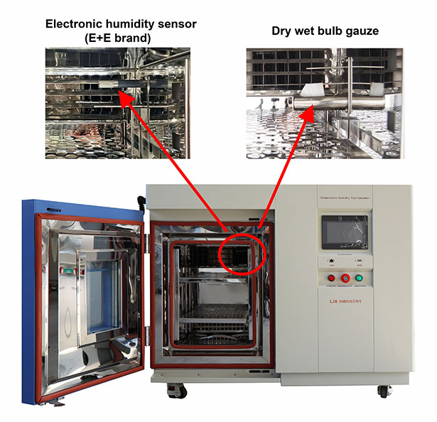
Temperature Range | A : -20℃ ~ +150 ℃ B : -40℃ ~ +150 ℃ C: -70℃ ~ +150 ℃ | |
Temperature Fluctuation | ± 0.5 ℃ | |
Temperature Deviation | ± 2.0 ℃ | |
Humidity Range | 20% ~ 98% RH | |
Humidity Deviation | ± 2.5% RH | |
Cooling Rate | 1 ℃ / min | |
Heating Rate | 3 ℃ / min | |
| Calibration Sensors | PT100 Class A Temperature Sensor and Capacitive Humidity Sensor | |
| Typical Calibration Points | 23°C/50% RH, 25°C/60% RH, 40°C/75% RH, 60°C/90% RH, 85°C/85% RH | |
Technicians deploy calibrated reference sensors throughout the chamber and compare their readings with:
The programmed setpoint
The chamber's control sensor
Other reference sensors positioned throughout the workspace
This process identifies hot spots, cold spots, humidity gradients, and airflow-related deviations that cannot be detected through single-point calibration.
A constant climate chamber can also be used as a stable environmental source for calibrating external sensors.
For example, humidity sensors may be positioned within a controlled humidity environment and compared with a high-accuracy reference instrument.

In this case, the constant climate chamber must first demonstrate adequate stability and spatial uniformity. Otherwise, differences between sensor readings could result from the chamber's environmental gradients rather than errors in the sensors being calibrated.
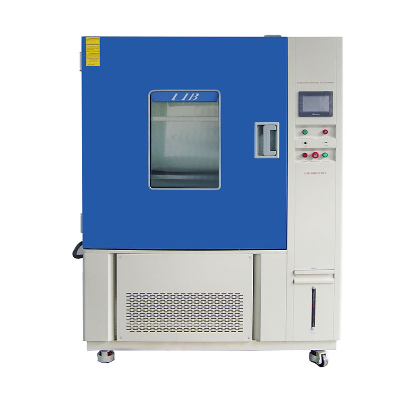
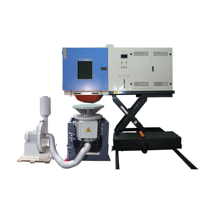
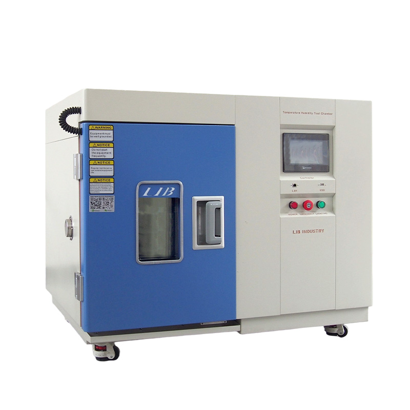
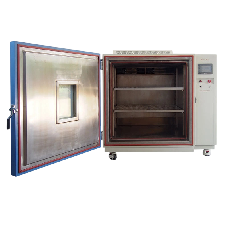
| LIB Popular Constant Climate Chambers | ||
Precise climate simulation, Reliable long-term stability testing |
Temperature and Humidity Calibration Chamber for Thermometers and Hygrometers Simulate temperature, humidity, and vibration stresses in one test |
Small temperature humidity chamber Compact footprint design, High-accuracy environmental control |
Industrial High-Temperature Vacuum Drying Oven Uniform heat distribution, Efficient material drying |
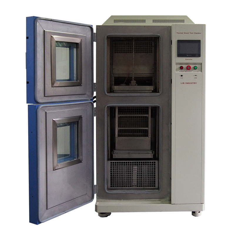
Extreme thermal stress simulation, Fast failure detection capability |
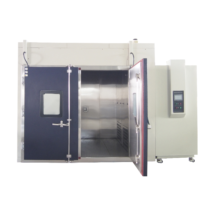
Large-capacity testing space, Ideal for oversized products |
Constant climate chambers may be used in pharmaceutical, electronics, materials, automotive, aerospace, and other regulated testing applications.
Depending on the application, relevant frameworks can include:
ICH Q1A
ISO/IEC 17025
FDA 21 CFR Part 211
IEC environmental testing requirements
These frameworks emphasize measurement traceability, documented procedures, controlled environmental conditions, and reliable calibration records.
For constant climate chambers, calibration records should demonstrate what test samples actually experienced rather than merely showing that the chamber controller displayed the correct setpoint.
Reference instruments used to calibrate constant climate chambers should have traceability to recognized national metrology standards such as NIST or equivalent national institutes.
An unbroken calibration chain should be maintained for:
RTDs
Thermocouples
Humidity reference instruments
Data acquisition systems
Other reference sensors
Without traceability, calibration results may be difficult to defend during audits.
The number and position of sensors depend largely on the size of the constant climate chamber. Guidelines such as DKD-R 5-7 or IEC 60068-3-5 may be used to establish suitable mapping arrangements. Typical layouts can include:
9-point grids
15-point grids
27-point volumetric grids
LIB Industry adopts a standardized 9-point grid for workspace calibration, in strict accordance with IEC 60068-3-5. Sensors are positioned at the eight corners of the usable workspace plus the geometric center, ensuring that temperature and humidity readings accurately represent the entire chamber volume rather than a single localized point. This approach provides a reliable, repeatable, and audit-ready basis for verifying spatial uniformity across every constant climate chamber we deliver.
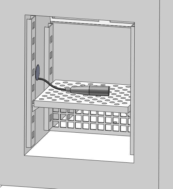
Sensors should be positioned strategically throughout constant climate chambers rather than simply wherever wiring is easiest. Important locations can include:
① Workspace corners
② Door-side areas
③ Upper and lower shelves
④ Airflow supply zones
⑤ Airflow return zones
⑥ Areas near baffles
⑦ Cable-port locations
⑧The geometric center
The objective is to identify worst-case positions within the usable workspace. For large walk-in constant climate chambers, more complex multi-level sensor grids may be required because of the larger internal volume. Technicians may also need robust sensor stands and carefully routed cables to prevent sensors from moving during the mapping process.
High-precision resistance temperature detectors (RTDs) are commonly used when mapping constant climate chambers because of their stability and accuracy. Reference sensors should have better accuracy than the equipment being calibrated. For example, if the required constant climate chamber tolerance is ±2°C, using a reference sensor with ±0.5°C accuracy provides a 4:1 accuracy relationship.
Humidity calibration may use instruments such as:
Chilled mirror hygrometers
High-accuracy capacitive RH sensors
Other calibrated humidity references
Chilled mirror hygrometers are often used as highly accurate reference instruments for humidity measurement.
Capacitive RH sensors provide faster response and can be useful when mapping changing humidity conditions inside constant climate chambers.
The Test Accuracy Ratio (TAR) and Test Uncertainty Ratio (TUR) help determine whether the calibration standard is sufficiently accurate relative to the constant climate chamber.
A 4:1 accuracy ratio is commonly considered a good target.
Reference instruments should not consume too much of the constant climate chamber's allowable tolerance.
| Sensor Technology | Primary Application | Accuracy Level | Response Time |
|---|---|---|---|
| Resistance Temperature Detectors (RTDs) | Spatial Temperature Mapping | Very High | Moderate |
| Chilled Mirror Hygrometers | Absolute Humidity Reference | Gold Standard | Slow |
| Capacitive RH Sensors | Dynamic Humidity Profiling | High | Fast |
| Thermocouples (Type T) | Extreme Temperature Conditions | Moderate | Fast |
A common starting point for stability testing equipment is a calibration interval of approximately 6 to 12 months.
However, constant climate chambers should not automatically follow the same interval regardless of operating conditions.
Calibration frequency can depend on:
Usage intensity
Test criticality
Regulatory requirements
Temperature and humidity extremes
Historical calibration results
Sensor drift
Chamber age
24/7 operation
Frequency of door opening
Maintenance history
For example, if a constant climate chamber shows substantial drift after 12 months during several consecutive calibration cycles, the facility may shorten the interval to nine or six months. Historical "As Found" data is particularly useful for establishing an appropriate calibration frequency.
Facilities can perform calibration internally or use external metrology providers.
Internal calibration can provide greater scheduling flexibility but requires investment in:
Reference instruments
DAQ equipment
Calibration software
Technician training
Instrument recertification
Calibration procedures
Traceability records
Facilities operating only a small number of constant climate chambers may find these costs difficult to justify.
Third-party calibration services can provide specialized equipment and trained technicians.
If a constant climate chamber fails calibration, qualified technicians may also be able to perform mechanical repairs, sensor adjustments, or component replacement.This can reduce downtime compared with separating calibration and maintenance into different service visits.External service providers may also be more practical for facilities operating large fleets of constant climate chambers or large walk-in units. ISO/IEC 17025-accredited calibration providers can offer independent validation and traceability documentation that may be useful during regulatory audits.
Proper calibration of constant climate chambers requires more than checking the controller display against a single reference sensor.
A reliable calibration program should evaluate spatial uniformity throughout the usable workspace, allow sufficient stabilization time, consider actual product loading conditions, use traceable reference instruments, and document both "As Found" and "As Left" results.
For facilities using constant climate chambers for pharmaceutical stability testing, electronics reliability testing, materials evaluation, or other controlled environmental applications, multi-point workspace mapping provides a more defensible representation of actual chamber performance.
LIB Industry recommends establishing calibration procedures according to the chamber size, operating range, loading condition, application requirements, historical drift data, and applicable testing standards.
Before the next calibration cycle:
Review whether your constant climate chamber calibration includes multi-point spatial mapping.
Analyze historical "As Found" data when determining calibration intervals.
Document loaded and empty operating conditions where relevant.
Establish door-opening and recovery procedures.
Verify that reference instruments have current calibration traceability.
Confirm that external service providers hold the appropriate accreditation when required.
Single-point calibration only measures conditions around one sensor. It cannot identify spatial gradients, hot spots, cold spots, or airflow dead zones throughout the workspace. Multi-point mapping gives a more complete representation of constant climate chamber performance.
Standard reach-in constant climate chambers generally require at least 30 to 60 minutes after reaching the target condition. Large walk-in chambers may require several hours because their walls, shelves, internal structures, and air volume take longer to reach equilibrium.
"As Found" data records constant climate chamber performance before adjustments are made. "As Left" data records performance after necessary corrections or adjustments and verifies whether the chamber now operates within the specified tolerance.
Calibration should reflect actual operating conditions. Empty calibration provides useful baseline information, while loaded calibration can identify airflow restrictions and thermal effects caused by products, packaging, shelves, or fixtures.
A 6-to-12-month interval is commonly used as a starting point. However, constant climate chambers used continuously, operated under severe temperature or humidity conditions, or supporting high-consequence testing may require shorter calibration intervals.
Technicians should identify the underlying cause, which may include sensor drift, degraded seals, airflow problems, or mechanical faults. After corrective action or controller adjustment, the spatial mapping process should be repeated to generate acceptable "As Left" calibration results.
If you're in the market for a constant climate chamber, whether it's a Constant Climate Chamber for Calibration of Thermometers and Hygrometers, a Temperature and Humidity Calibration Chamber for Thermometers and Hygrometers, or a Walk-In Temperature Humidity Chamber, don't hesitate to reach out. We're ready to discuss your workspace size, temperature and humidity range, calibration requirements, and loading conditions, and help you find the right constant climate chamber solution for your laboratory.
LIB Industry Technical Team, Technical information, testing methods, product specifications, and application guidance for constant climate chamber and calibration equipment.