Views: 0 Author: LIB Team Publish Time: 2026-08-13 Origin: Site


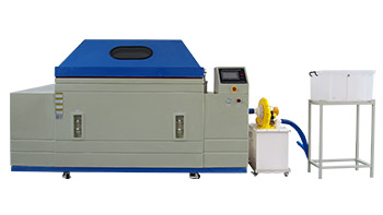
The defensibility of any accelerated corrosion test relies entirely on the strict control of internal chamber variables, with fog dispersion being the most critical and frequently scrutinized metric. Inconsistent or unverified fog collection rates lead to invalid test data, false passes/failures in product QA, and immediate non-compliance with stringent international standards like ASTM B117 and ISO 9227. Ensuring accurate fog deposition requires a combination of rigorous manual verification protocols and selecting a properly engineered Salt Spray Test Chamber designed for uniform atomization and reliable condensate tracking. Without precise measurement and control of the fallout rate, the corrosive environment becomes unpredictable, rendering any comparative analysis or historical data completely useless for quality assurance and material validation.
Standardized Baselines: ASTM B117 dictates a strict fog collection rate of 1.0 to 2.0 mL per hour per 80 cm² of horizontal collection area.
Verification Frequency: Collection rates, specific gravity, and pH must be measured and recorded at least daily, with weekly titrations recommended to verify sodium chloride concentration.
Equipment Impact: The internal geometry, atomizer design, and airflow dynamics of your chosen test cabinet directly dictate how easily and consistently these collection rates can be maintained.
Risk Mitigation: Improper placement of collection funnels—such as in the "shadow" of test specimens or in areas prone to dripping—is the leading cause of skewed verification data.
The volume of salt fog settling on a specimen shares a direct correlation with the accelerated corrosion rate observed during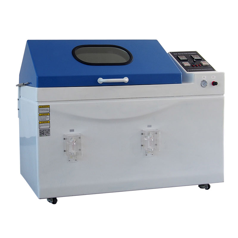 testing. A test chamber must deliver a highly specific amount of corrosive mist to simulate long-term environmental exposure accurately. Deviations from this target volume compromise the comparative baseline of the entire test. If the environment is too wet, the continuous washing effect can remove corrosion products prematurely. If it is too dry, the required corrosive electrolyte layer fails to form adequately. Both scenarios render historical data and cross-laboratory comparisons completely useless.
False passes present a massive liability for manufacturers of high-specification materials. Industrial coatings, marine paints, electroplated fasteners, and military-grade components tested under MIL-STD-810 require absolute certainty. Approving a defective coating because the chamber failed to deliver enough salt fog can lead to catastrophic field failures, expensive recalls, and damaged brand reputation. Strict verification of the fog collection rate is the only way to prove the test environment met the required severity.
To further illustrate the impact of collection rates on test validity, consider the mechanics of electrolyte formation on the specimen surface. The salt fog must condense at a rate that maintains a continuous, thin film of moisture. This film acts as the conductive medium for the electrochemical corrosion process. If the collection rate falls below 1.0 mL/hr, the film may evaporate in localized areas, halting the corrosion reaction and leading to artificially extended survival times for the coating. Conversely, a rate exceeding 2.0 mL/hr can create a flowing layer of water that washes away the very chloride ions necessary to sustain the attack, again skewing the results toward a false pass.
International testing standards define exact volumetric requirements to ensure global consistency. ASTM B117 mandates a collection rate of 1.0 to 2.0 mL per hour over an 80 cm² horizontal area. This specific metric ensures that the fallout is dense enough to maintain continuous surface wetting without causing excessive runoff. Achieving this requires continuous atomization, a stable chamber temperature typically held at 35°C (95°F), and uninterrupted testing cycles during the measurement period.
Operational parameters must remain tightly controlled during the collection phase. Continuous salt spray testing requires a steady state, whereas cyclic corrosion testing involves intermittent fog cycles. Monitoring collection in a cyclic test requires measuring only during the active fog generation phases and calculating the hourly average based strictly on that active time. Failing to account for dry or dwell cycles will result in artificially low collection rate calculations.
The 80 cm² standard area is not arbitrary; it represents a practical surface area for capturing a representative sample of the fog fallout without disrupting the airflow dynamics within the chamber. When setting up the verification apparatus, technicians must ensure that the funnels used match this area or that the collected volume is mathematically normalized to this standard. This mathematical normalization is a frequent point of failure during laboratory audits, as technicians sometimes record the raw volume without adjusting for the actual funnel diameter.
Accurate verification begins with the strategic placement of collection receptacles. Standards require at least two clean fog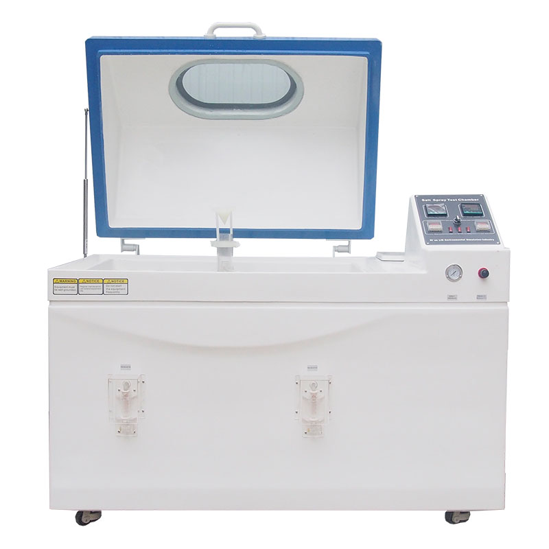 collectors per atomizer within the neutral salt fog equipment. One collector must be placed nearest to the nozzle to capture the heaviest initial fallout, while the other is placed farthest from the nozzle to verify adequate dispersion at the chamber's extremities. This dual-placement strategy ensures the entire testing zone receives uniform coverage.
Collectors must never be placed where they can gather drops from test specimens, chamber ceilings, or internal supports. Placing a funnel in the "shadow" of a large test piece will block the fog, resulting in a falsely low reading. Conversely, positioning a funnel under a dripping sample rack will cause a falsely high reading. Receptacles must sit in clear, unobstructed areas at the same horizontal plane as the test specimens.
Measuring collected condensate requires a defined time period to establish a reliable average. A minimum of 16 hours of continuous operation is highly recommended to smooth out minor fluctuations in atomization. After the collection period, the technician measures the total volume in the graduated cylinder and divides it by the total hours to find the hourly rate.
Verify the funnel diameter using a calibrated caliper.
Calculate the collection area using the formula for the area of a circle (πr⊃2;).
Record the total volume of condensate collected over the 16-hour period.
Divide the total volume by the number of hours to determine the raw hourly rate.
Normalize the raw rate to the 80 cm² standard by multiplying the raw rate by 80 and dividing by the actual funnel area.
Physical calculation formulas are necessary if your funnels do not exactly match the 80 cm² standard. Measure the funnel diameter to calculate its area. A standard 100 mm (10 cm) diameter funnel yields a horizontal collection area of approximately 78.5 cm². To normalize the collection volume mathematically to the standard 80 cm² requirement, multiply the collected hourly volume by 80, then divide by the actual area of your funnel. This ensures strict mathematical compliance with ASTM B117.
Volume alone does not guarantee compliance; the chemical makeup of the collected fog must also be verified. Technicians must test the collected solution at the standard operating temperature of 35°C (95°F). At this temperature, the specific gravity must fall between 1.025 and 1.040. If the temperature of the collected solution drops before measurement, the specific gravity reading will skew higher, requiring temperature correction tables.
Verification of pH is equally critical. For neutral salt fog, the pH must remain between 6.5 and 7.2. This is measured using electrometric measurement devices or precisely calibrated colorimetric paper. The pH of the collected solution often differs slightly from the reservoir solution due to the loss of carbon dioxide during atomization or interactions with the chamber environment. Adjustments must be made to the reservoir solution to ensure the collected fog remains within the specified neutral range.
Specific gravity provides a quick daily check, but weekly chemical titrations are recommended to verify the exact sodium chloride concentration. This process typically involves titrating the collected fog solution with silver nitrate to confirm it maintains the required 5% (± 1%) NaCl concentration. Titration provides a definitive chemical analysis of the salt content.
Relying solely on specific gravity for long-term compliance verification is insufficient. Temperature fluctuations, evaporation, and minor impurities can mask actual sodium chloride concentration changes. A solution might show an acceptable specific gravity while actually containing a lower salt concentration and higher levels of other dissolved solids. Weekly titrations eliminate this ambiguity.
The heart of any ASTM corrosion test cabinet is its atomization system. Precision-machined acrylic or polycarbonate nozzles are vastly superior to older metal designs. These advanced materials prevent salt crystal buildup at the orifice, which is the primary cause of erratic fog dispersion. A clean, unobstructed nozzle ensures a consistent fog plume, leading to highly stable collection rates over multi-week tests without requiring constant manual unclogging.
The design of the dispersion tower also plays a critical role in fallout uniformity. The tower must direct the atomized mist upward, allowing the heavier droplets to fall back into the reservoir while the fine, buoyant fog fills the chamber workspace. If the tower is improperly baffled, the mist will shoot laterally, causing high collection rates near the nozzle and dry zones at the chamber edges.
Traditional manual collection relies on graduated cylinders placed directly inside the workspace. Checking these requires opening the chamber, which immediately disrupts the thermal and humidity environment, pausing the test and potentially altering the corrosion rate. Modern chambers feature automated, externally visible collection monitoring systems. Funnels inside the chamber route the condensate to external graduated cylinders or digital sensors.
| Feature | Manual Collection | Automated External Collection |
|---|---|---|
| Test Disruption | High (requires opening chamber) | None (monitored externally) |
| Labor Intensity | High (daily manual checks) | Low (quick visual or digital check) |
| Data Accuracy | Prone to human error and thermal disruption | Highly stable, continuous monitoring |
| Maintenance | Requires frequent cleaning of internal cylinders | External components are easier to access |
The trade-off between these systems is clear. Manual systems are inexpensive but require test disruption and higher labor costs for daily checks. Automated systems increase upfront equipment costs but significantly reduce labor. More importantly, external monitoring preserves the internal environment, ensuring that the 35°C temperature and continuous fog remain completely uninterrupted during verification.
Internal geometry plays a massive role in maintaining accurate collection rates. Peaked or V-shaped chamber lids are mandatory design features. They force condensation to run down the interior walls rather than dripping onto test specimens or into the collection funnels. A single drop of condensate from a flat ceiling into a collection funnel will instantly ruin a 24-hour verification metric.
Internal baffling and aerodynamic design are also critical for preventing dead zones where fog fails to settle, or heavy fallout zones where it pools excessively. Properly engineered baffles direct the atomized plume upward and outward, allowing it to fall uniformly across the entire workspace. This ensures that a funnel placed near the nozzle reads similarly to one placed at the far end of the cabinet.
Fog collection rates are highly sensitive to temperature variations. Chamber heating configurations, such as water jacket heating versus dry wall heating, dictate thermal uniformity. Water jackets provide highly stable, even heat distribution, minimizing cold spots. Dry wall heaters must be carefully calibrated to avoid localized hot spots near the heating elements.
Temperature variations directly alter condensation rates. If a section of the chamber is too cool, the fog will condense more rapidly in that area, artificially spiking the collection rate. If an area is too hot, evaporation increases, dropping the collection rate below the 1.0 mL/hr minimum. Robust thermal control is non-negotiable for stable fog deposition.
| LIB Popular Environmental Chamber for Meatal and Paints | |||
 |  |
| 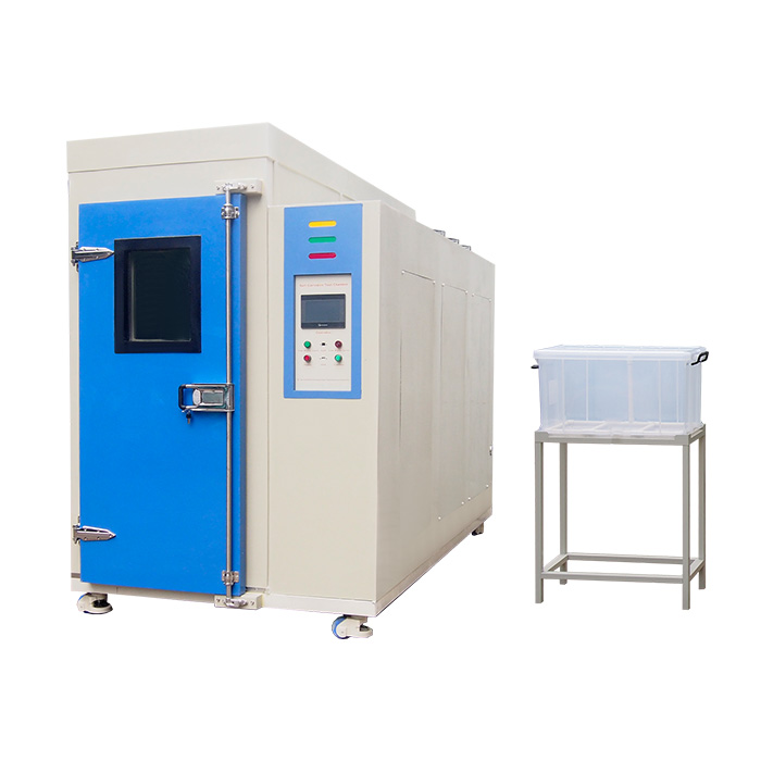 |
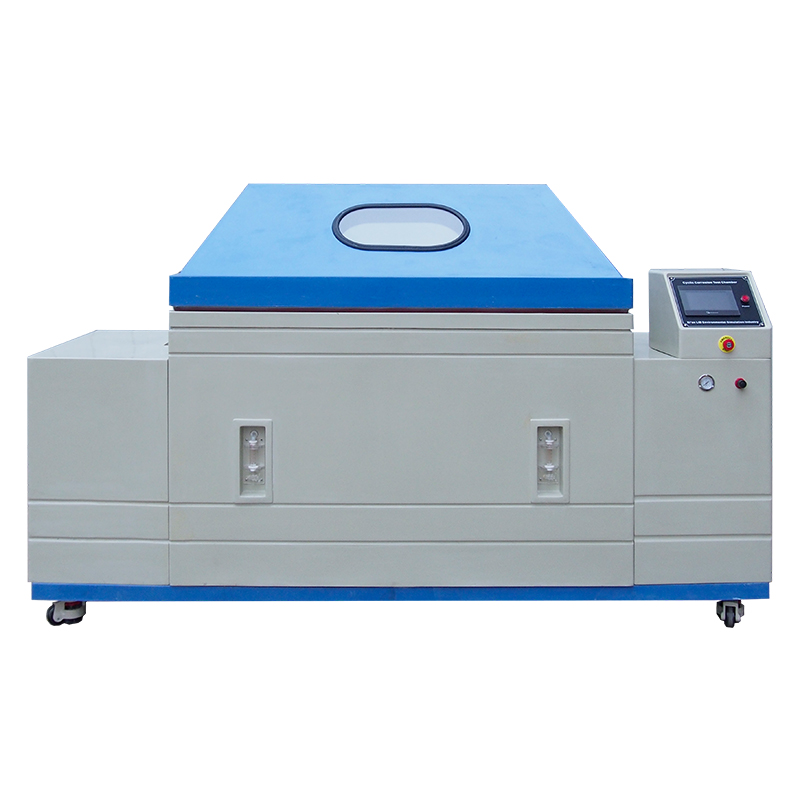
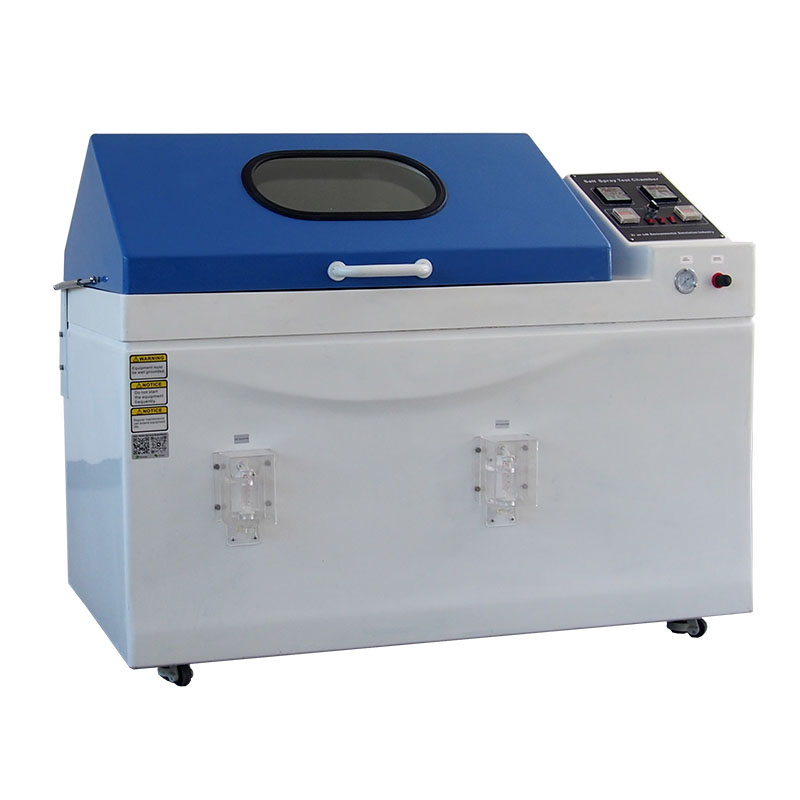
Cyclic Salt Spray Corrosion Chamber Realistic Wet-Dry Corrosion Simulation, Accelerated Corrosion Testing for Long-Term Durability | ASTM B117 Fog Corrosion Salt Spray Test Cabinet Reliable Salt Fog Exposure Testing, Accurate Corrosion Resistance Evaluation | Salt Spray and Sulfur Dioxide Climatic Chamber Simulate Acid Rain and Industrial Pollution, Advanced SO₂ Corrosion Testing Solution | Walk-in Salt Spray Corrosion Chamber Large-Capacity Corrosion Testing Space, Ideal for Oversized Components and Assemblies |
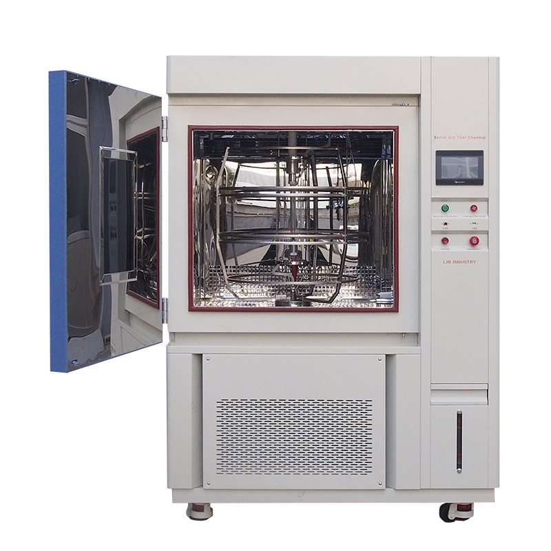 | 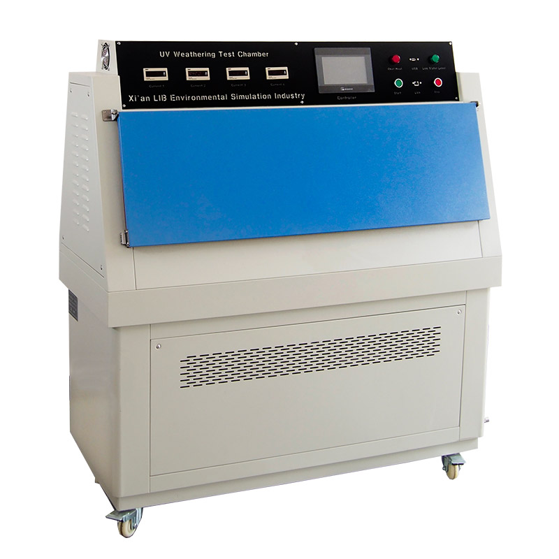 |  |  |
ASTM G155 G151 Accelerated Weathering XenonTest Apparatus Full-Spectrum Sunlight Simulation, Accelerated Outdoor Weathering Analysis | UVA 340 Fluorescent Lamp Light Fastness Test Instrument Precise UV Aging Performance Testing, Reliable Material Durability Verification | Temperature Humidity Test Chamber Stable Environmental Conditioning, Accurate Temperature and Humidity Control | Compact Mini Temperature Stability Climatic Test Chamber Space-Saving Laboratory Solution, High-Precision Climate Simulation in a Compact Design |
Encountering sub-1.0 mL/hr readings is a common challenge. The most frequent culprits are partial nozzle blockages caused by crystallized salt or debris. Inadequate compressed air pressure will also fail to siphon enough solution from the reservoir. Additionally, temperature drops from malfunctioning heating elements can reduce the overall humidity, while a depleted salt solution reservoir will obviously halt fog production entirely.
Mitigation requires strict maintenance routines. Technicians should perform regular nozzle inspections and cleaning. Inline air filters must be checked and drained of moisture or oil, which can disrupt atomization. Implementing automated reservoir level alarms prevents the system from running dry during unmonitored overnight or weekend shifts.
Readings exceeding 2.0 mL/hr indicate an over-saturating environment. This is typically caused by over-pressurized atomization air pushing too much solution through the nozzle. Over-heated chamber zones can also cause rapid, localized condensation. Another common issue is the direct impingement of the fog plume into the collection funnel due to improper baffle positioning.
Correcting high rates involves precise calibration adjustments. Lower the air pressure at the regulator slightly and monitor the results over the next several hours. Reposition the dispersion tower or internal baffles to ensure the fog plume is directed upward rather than shooting laterally toward the collection receptacles.
The integrity of the verification process demands pristine collection equipment. There is a high risk of cross-contamination if collection funnels and cylinders are not thoroughly cleaned between test cycles. Residual salt buildup or corrosion byproducts from previous tests will alter the pH and specific gravity readings of the newly collected fog.
Furthermore, standard protocols dictate an absolute prohibition on reusing collected salt fog solution. Once the fog has condensed and been collected, it has interacted with the chamber environment and potentially the test specimens. Reintroducing this solution into the reservoir will contaminate the entire test, invalidating all subsequent data.
Verifying the fog collection rate is the fundamental proof that a salt spray test chamber is operating within the strict tolerances required for defensible corrosion analysis. Without accurate collection data, any pass or fail result is scientifically meaningless and highly vulnerable to audit failures. Maintaining these parameters requires diligent manual checks and reliable equipment.
Audit your current verification protocols against ASTM B117 requirements to ensure mathematical normalization of collection areas.
Assess the consistency of your historical collection data to identify any recurring dead zones or pressure issues within the workspace.
Consult with equipment manufacturers about upgrading to systems with external or automated collection rate monitoring to protect test integrity.
Implement a strict weekly titration schedule to verify sodium chloride concentration beyond basic specific gravity checks.
A: ASTM B117 requires a fog collection rate of 1.0 to 2.0 mL per hour per 80 cm² of horizontal collection area. This ensures a consistent, continuous wetting of the test specimens without excessive runoff.
A: Collection rates, along with specific gravity and pH of the collected solution, must be measured and recorded at least daily during continuous testing to ensure ongoing compliance.
A: Atomization and evaporation within the heated chamber can change the concentration of the salt solution. Measuring the collected fog ensures the actual mist settling on the specimens meets the required 5% concentration.
A: No. Collected salt fog solution must never be reused. It has been exposed to the chamber environment and potentially contaminated by corrosion byproducts, which would invalidate future testing.
A: Uneven distribution is typically caused by clogged atomizer nozzles, improper baffle positioning, poor chamber geometry, or placing large test specimens that block the fog plume and create dry shadows.
A: Temperature directly affects condensation and evaporation. Cold spots cause rapid condensation, artificially increasing collection rates, while hot spots increase evaporation, dropping the collection rate below standard requirements.
Need a salt spray chamber designed for stable fog dispersion, accurate collection-rate verification, and repeatable corrosion testing? LIB Industry provides salt spray and cyclic corrosion test chambers for ASTM B117, ISO 9227, and other international corrosion testing requirements. Contact LIB Industry for customized salt spray testing solutions, equipment selection, and technical support.