Views: 0 Author: LIB Team Publish Time: 2026-08-28 Origin: Site


Non-repeatable testing carries severe financial and compliance consequences. Invalidated data, delayed product launches, and false positives or negatives in reliability testing can derail manufacturing schedules. Reaching a target temperature or humidity is relatively simple. Maintaining spatial uniformity and temporal stability across hundreds of cycles—especially with live, heat-dissipating loads—is a complex engineering challenge for environmental chambers.
Before procurement, you should evaluate the underlying mechanics, sensor architecture, power control systems, and control algorithms of environmental test chambers. At LIB Industry, environmental chambers are considered not only by whether they can reach a setpoint, but also by whether they can maintain stable, repeatable conditions over time under dynamic stress. This is essential when testing must follow strict industry standards such as MIL-STD, IEC, and ASTM.
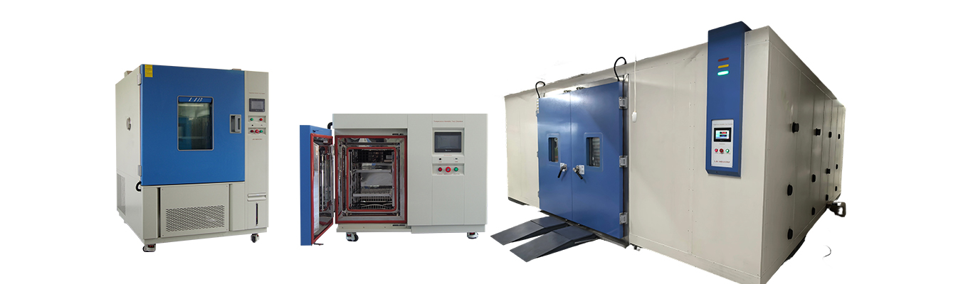
Repeatability relies on tight PID control: Environmental chambers should utilize advanced Proportional-Integral-Derivative (PID) algorithms to anticipate and correct environmental drift before it breaches tolerances.
Airflow dictates uniformity: Environmental chambers require high-velocity, strategically baffled airflow to eliminate microclimates and maintain spatial uniformity across the workspace.
Sensor selection and protection matter: Long-term repeatability in environmental chambers requires low-drift sensors, such as Class A PT100 RTDs, with robust, hermetically sealed sheathing.
Power regulation stabilizes heating cycles: Environmental chambers using advanced SCR (Silicon Controlled Rectifier) power controllers can reduce the micro-oscillations associated with basic SSR control.
Maintenance prevents degradation: Even well-designed environmental chambers can lose repeatability without appropriate calibration schedules, seal inspections, and utility water quality control.
Evaluating environmental chambers requires distinguishing between three performance metrics. Accuracy measures how close the average condition is to the programmed setpoint. Spatial uniformity defines the variance in conditions between different physical locations inside the chamber at a single point in time. Temporal repeatability is the ability to reproduce the same accuracy and uniformity profile across multiple identical test cycles over months or years. Environmental chambers need all three characteristics for valid, defensible test data.
Many facilities confuse accuracy with uniformity when evaluating environmental chambers. A single sensor might read exactly 85°C, showing perfect accuracy. However, the corners of the workspace might be sitting at 82°C due to poor airflow. If you place a product in that corner, the test may no longer represent the required condition. Repeatability means that if environmental chambers run a 1000-hour damp heat test today and repeat the same profile six months from now, the thermal gradients and control lines should remain comparable.
| Performance Metric | Definition | Field Impact |
|---|---|---|
| Accuracy | Proximity of the control sensor reading to the target setpoint. | Ensures the baseline test requirement is met at the control point. |
| Spatial Uniformity | Temperature/humidity variance across the internal workspace. | Guarantees all samples experience the same stress regardless of shelf position. |
| Temporal Repeatability | Consistency of accuracy and uniformity over successive test cycles. | Allows historical data comparison and validates long-term reliability metrics. |
The mass of the Device Under Test (DUT) and active heat dissipation can disrupt baseline repeatability in environmental chambers. A heavy, dense DUT, such as a solid aluminum engine block or a large battery module, absorbs heat slowly and lags behind the air temperature. Active loads, such as powered electronics or RF amplifiers, continuously introduce heat into the workspace. Environmental chambers must dynamically compensate for these variables.
When environmental chambers test a 500W active load, the cooling system must run continuously just to maintain steady-state conditions. If the cooling system lacks proportional control, it can over-cool the air, forcing the heaters to compensate. This creates a sine wave of temperature fluctuations. Highly repeatable environmental chambers adjust cooling capacity in real time to match the live load, helping maintain a flatter control line without overshooting or producing localized hot spots.
Airflow directly affects uniformity in environmental chambers. Fan speed, baffle placement, and aerodynamic design help prevent stratification and dead zones. High-velocity air must sweep across the DUT to remove boundary layers of heat. When selecting environmental chambers, you should evaluate the trade-offs between horizontal and vertical airflow based on shelving configurations and DUT geometry.
Solid shelves can block vertical airflow and create severe microclimates inside environmental chambers. Wire racks allow better circulation. In a vertical airflow system, air typically enters from the bottom and exits the top. If the bottom shelf is heavily loaded, the top shelves may receive less conditioned air. Horizontal airflow, where air moves from right to left across each shelf independently, can provide better uniformity for densely packed loads. The blower motor in environmental chambers must also maintain sufficient cubic feet per minute (CFM) when the workspace is heavily loaded.
Traditional on/off compressor cycling can cause aggressive temperature swings in environmental chambers. When the compressor engages, it delivers full cooling capacity. The temperature may fall below the setpoint, the compressor then shuts off, and the heaters engage to recover. This binary approach can reduce repeatability.
Modern environmental chambers may use electronic expansion valves (EEVs) and hot gas bypass valves to support smaller cooling adjustments. Proportional cooling matches the cooling output more closely to the actual heat load. The controller modulates the EEV to restrict refrigerant flow, delivering only the capacity required to hold the setpoint. This helps environmental chambers prevent temperature dips below the target and maintain a smoother control line for tight-tolerance testing.
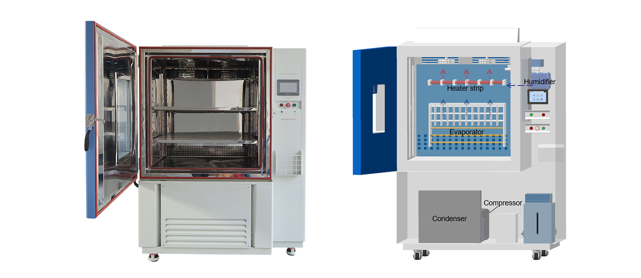
Heating control is just as important as cooling for environmental chambers. SCR (Silicon Controlled Rectifier) power controllers offer advantages over standard SSRs (Solid State Relays). Phase-angle or burst-fire SCR control provides variable, proportional power to heating elements. In environmental chambers, this can reduce thermal shock and stabilize the micro-climate during critical dwell periods.
| Controller Type | Operation Mechanism | Impact on Repeatability |
| Solid State Relay (SSR) | Binary on/off duty cycling, such as 1 second on and 1 second off. | Can cause micro-fluctuations; acceptable for basic testing but less suitable for tight tolerances. |
| Silicon Controlled Rectifier (SCR) | Proportional power delivery that modulates the voltage waveform. | Provides more precise heat input, reducing thermal shock and supporting flatter control lines. |
Humidity stability is another important factor in environmental chambers. Vapor generators boil water to introduce pure steam, while atomizing systems spray fine mists. Vapor systems generally provide smoother control and are less prone to introducing unevaporated water droplets onto the DUT. Environmental chambers operating at low humidity may also require a desiccant dryer or purge air system to avoid frost buildup or sudden dew point shifts.
When environmental chambers operate at 10% relative humidity and 20°C, the dew point is extremely low. Standard cooling coils may freeze while trying to maintain the required condition. A desiccant dryer strips moisture from the air chemically, helping environmental chambers maintain low dew points without relying solely on the refrigeration system for dehumidification.
| LIB popular Temperature Humidity Chambers | |||
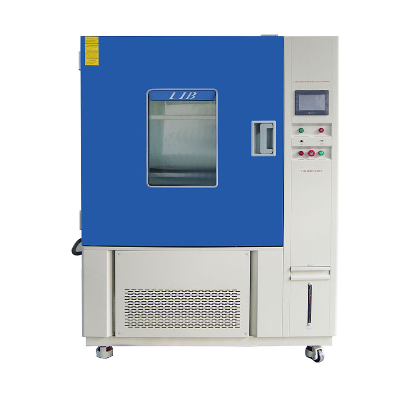
Standing temperature humidity chamber Precise climate simulation, Reliable long-term stability testing |
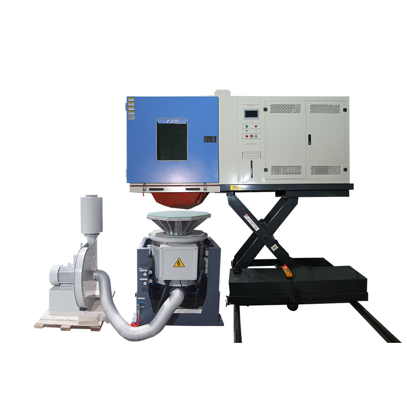
Combined Climate and Vibration Chamber Simulate temperature, humidity, and vibration stresses in one test |
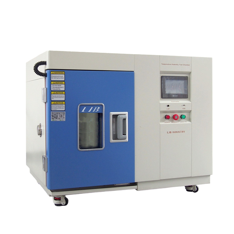
Small temperature humidity chamber Compact footprint design, High-accuracy environmental control |
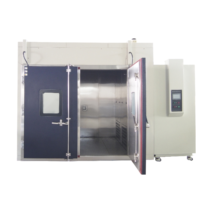
Walk-In temperature humidity chamber Large-capacity testing space, Ideal for oversized products |
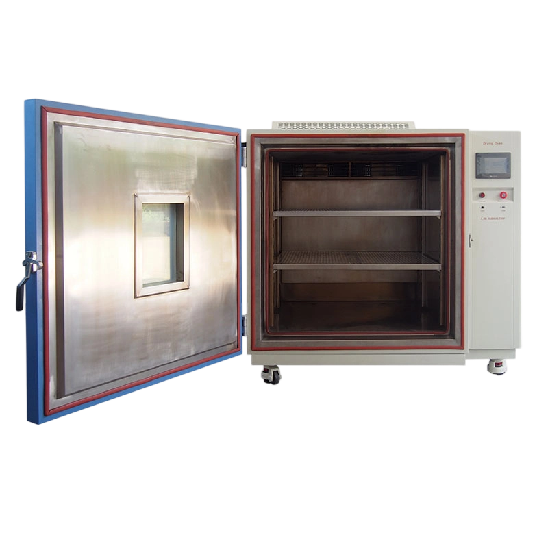
Industrial High-Temperature Vacuum Drying Oven Uniform heat distribution, Efficient material drying |
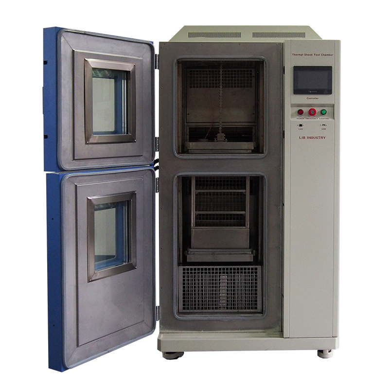
Extreme thermal stress simulation, Fast failure detection capability |
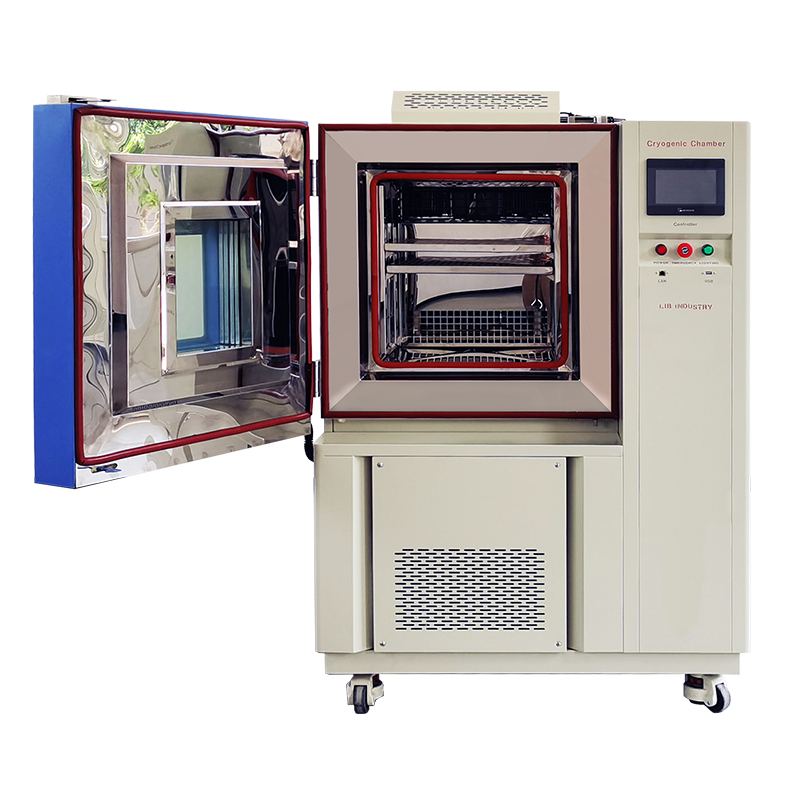
Ultra-low temperature performance, Reliable cold resistance evaluation |
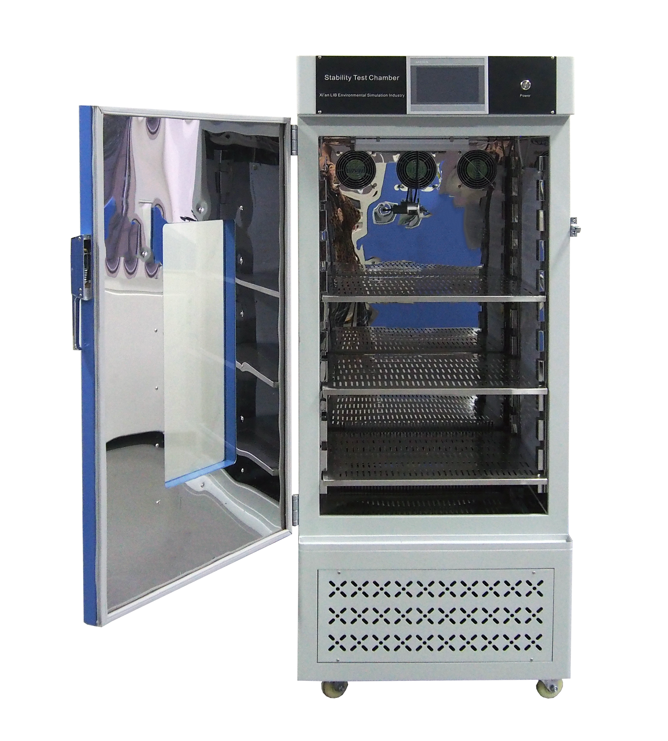
ICH-compliant stability testing, Precise temperature and humidity control |
Resistance Temperature Detectors (RTDs), specifically PT100s, are preferred for long-term stability and minimal drift compared with standard thermocouples. Thermocouples degrade faster over time due to metallurgical changes in the wire and have wider inherent error bands. For environmental chambers expected to support repeatable testing over years, the precision and stability of a Class A PT100 RTD can be critical.
A Type T thermocouple might have an error of ±1.0°C out of the box. A Class A PT100 RTD has an error of ±0.15°C at 0°C. When environmental chambers must maintain a chamber tolerance of ±0.5°C, a sensor with a wide inherent error range can consume a significant portion of the tolerance band.
Sensor construction also influences the long-term repeatability of environmental chambers. Sheathing materials such as 316 stainless steel or Inconel protect delicate internal sensing elements. Hermetic glass sealing protects RTD elements from chemical off-gassing and moisture infiltration under high-humidity conditions.
If moisture penetrates the sensor sheath, it can alter the resistance reading. The controller may interpret the chamber as colder than it actually is and apply unnecessary heat. A compromised sensor can drift unpredictably, reducing the repeatability of environmental chambers. Always verify the IP rating and construction materials of the primary control sensors.
Wet/dry bulb systems are highly accurate but require rigorous maintenance. Solid-state capacitive sensors offer lower maintenance but require regular calibration to correct for drift. The right choice for environmental chambers depends on a facility's maintenance capabilities and the required humidity range.
1. Wet/Dry Bulb Maintenance: The cotton wick must be replaced regularly, often weekly, depending on test conditions.
2. Water Purity: Wet bulb systems require strict deionized water purity to prevent mineral buildup on the wick.
3. Capacitive Sensor Calibration: Solid-state sensors must be calibrated against a chilled mirror hygrometer annually to correct for chemical degradation of the dielectric layer.
4. Low Humidity Limits: Capacitive sensors generally perform better at extreme low humidity, below 10% RH, where wet bulb depression becomes difficult to measure accurately.
The physical location of the control sensor impacts the actual conditions experienced by the DUT inside environmental chambers. A sensor in the supply air stream reacts faster to chamber changes and can help prevent overshoots. A sensor in the return air stream better reflects the average condition after air has passed over the load.
Independent product-temperature sensors attached directly to the DUT are necessary for critical evaluations. You cannot assume the product is at 85°C simply because the air is at 85°C. A laboratory climate test equipment setup should include multiple thermocouple inputs to monitor the actual thermal mass of the product. For repeatable environmental chambers, these measurements help verify what the DUT actually experiences during each test cycle.
Modern environmental chambers use cascading PID loops to manage competing systems, such as heating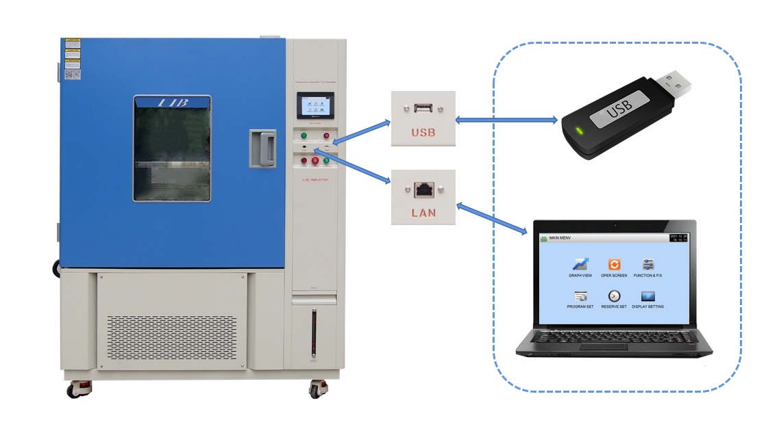 and cooling simultaneously, and to maintain tight tolerances. The PID algorithm calculates the difference between the setpoint and the actual temperature, then adjusts output proportionally. Proper tuning helps environmental chambers prevent overshoots during rapid temperature ramps and maintain stability during long soak periods.
The Proportional band dictates how aggressively the system responds to an error. The Integral term corrects steady-state offsets over time. The Derivative term anticipates future errors based on the current rate of change. Poorly tuned environmental chambers can oscillate around the setpoint. Advanced controllers can auto-tune these parameters based on the thermal mass of the current load.
Advanced controllers in environmental chambers allow multi-point sensor calibration offset entries directly into the software. This linearizes sensor response and corrects known drift across the operating range. Instead of using only a single offset, environmental chambers can apply corrections at multiple temperatures.
A sensor might read correctly at 25°C but read 1.5°C high at 150°C. If only a single-point offset is applied at ambient temperature, high-temperature tests may still be inaccurate. Multi-point correction allows environmental chambers to apply the appropriate mathematical offset based on the current operating temperature.
Proving repeatability requires environmental chambers to support secure, high-resolution data logging. Software compliance features, such as 21 CFR Part 11, provide electronic signatures and unalterable logs for regulated industries. The controller should record setpoints, actual values, and system alarms at frequent intervals.
Logging data once per minute is standard, but rapid thermal shock tests may require logging every second. Data should be exportable in a secure format that prevents tampering. If an auditor questions the validity of a test run from two years ago, environmental chambers with appropriate data logging should provide the exact thermal profile showing whether the chamber remained within tolerance.
The controller manages transition phases in environmental chambers. LIB Industry's truly repeatable programmable testing chamber must maintain linear ramp rates despite changes in ambient laboratory conditions. Environmental chambers should dynamically adjust heating or cooling power to maintain the programmed rate of change.
If you program a 3°C-per-minute ramp, the controller must maintain that ramp as closely as required by the test method. If the laboratory ambient temperature is unusually high, the cooling system must work harder. The controller monitors the rate of change and adjusts EEV or SCR output continuously so environmental chambers can follow the same thermal profile from one test cycle to the next.
| Model | TH-100 | TH-225 | TH-500 | TH-800 | TH-1000 |
| Internal Dimension (mm) | 400*500*500 | 500*600*750 | 700*800*900 | 800*1000*1000 | 1000*1000*1000 |
| Overall Dimension (mm) | 900*1050*1620 | 1000*1140*1870 | 1200*1340*2020 | 1300*1540*2120 | 1500*1540*2140 |
| Interior Volume | 100L | 225L | 500L | 800L | 1000L |
| Heat load | 1000W | ||||
| Temperature Range | A : -20℃ ~ +150 ℃ | ||||
| B : -40℃ ~ +150 ℃ | |||||
| C: -70℃ ~ +150 ℃ | |||||
| Temperature Fluctuation | ± 0.5 ℃ | ||||
| Temperature Deviation | ± 2.0 ℃ | ||||
| Humidity Range | 20% ~ 98% RH | ||||
| Humidity Deviation | ± 2.5% RH | ||||
| Cooling Rate | 1 ℃ / min | ||||
| Heating Rate | 3 ℃ / min | ||||
| Cooling system | Mechanical compression refrigeration system | ||||
| Refrigerating unit | French TECUMSEH compressor | ||||
| Heating Element | Nichrome heater | ||||
| Controller | Programmable color LCD touch screen controller, Ethernet connection | ||||
| Water supply system | Automatic water supply, Water purification system | ||||
| Humidifier | External isolation, stainless steel surface evaporation humidifier | ||||
| Safety Device | Humidifier dry-combustion protection; over-temperature protection; over-current protection; Refrigerant high-pressure protection; Water shortage protection; Earth leakage protection | ||||
| Exterior Material | Steel Plate with protective coating | ||||
| Interior Material | SUS304 stainless steel | ||||
| Thermal Insulation | Polyurethane foam and insulation cotton | ||||
| Observation Window | Interior lighting, double-layer thermo stability silicone rubber sealing | ||||
| Standard Configuration | 1 Cable hole with plug; 2 shelves | ||||
Sensor drift is a primary threat to repeatability in environmental chambers. ISO/IEC 17025 accredited calibration and the use of NIST-traceable reference standards help verify measurement accuracy. Extending calibration cycles can increase the risk of testing products under out-of-tolerance conditions and invalidating data.
Sensors can drift due to thermal cycling fatigue, mechanical vibration, and chemical exposure. A PT100 RTD might drift 0.1°C per year under normal use, while aggressive thermal shock profiles can accelerate this process. Regular calibration against a known standard allows environmental chambers to identify drift and apply corrections through controller software.
Worn door gaskets or unsealed cable ports allow ambient laboratory air to enter environmental chambers. This can disrupt humidity stability, cause localized condensation, and force the control system to work harder. Regular seal inspection and replacement are therefore important preventive maintenance tasks.
Silicone door gaskets take a compression set over time. They lose elasticity and may no longer form a tight seal. During low-temperature testing, ambient moisture can enter environmental chambers through small leaks. The moisture may freeze on cooling coils, reducing efficiency and causing temperature drift.
Poor deionized (DI) water quality can cause scale buildup in humidity generators, reducing efficiency and creating erratic humidity control in environmental chambers. Voltage fluctuations can also affect compressor efficiency, heater output, and controller accuracy. Voltage regulation and water-quality monitoring are important for maintaining long-term stability.
Humidity systems require water with a specific resistivity, typically between 1 and 10 Megohm-cm. If the water is too pure, such as 18 Megohm-cm, it can become highly aggressive and leach ions from stainless steel plumbing, causing pitting and leaks. If the water is too dirty, calcium and magnesium deposits may insulate vapor-generator heaters and contribute to failures. Stable utilities help environmental chambers maintain repeatable humidity performance over extended operation.
Repeatable environmental chambers depend on more than reaching a target setpoint. Buyers should evaluate airflow design, proportional heating and cooling control, sensor stability, calibration capability, data logging, seal condition, and facility utilities. LIB Industry recommends matching the capacity and control architecture of environmental chambers to the actual DUT mass, active heat dissipation, required ramp rate, and long-term testing profile.
Before finalizing a purchase, request factory uniformity maps such as 9-point thermocouple surveys and compare the heating and cooling capacity of environmental chambers with your specific live-load requirements rather than relying only on nominal specifications.
Consult application engineers to run a simulated thermal load calculation based on your specific DUT mass and active heat dissipation.
Specify industrial-grade measuring instruments, particularly Class A PT100 RTDs, and verify the sensor protection methods used in environmental chambers.
Define a preventive maintenance and calibration schedule, including ISO 17025 accredited procedures, before finalizing the purchase.
Verify that facility utilities, especially power stability and DI water resistivity, meet the requirements of the humidity generation system.
A: Standard tolerances typically range from ±0.5°C to ±2.0°C depending on the specific test standard. It is important to differentiate between control tolerance, which measures stability at the sensor, and spatial uniformity, which measures variance across the workspace of environmental chambers.
A: Annual or bi-annual calibration is recommended depending on usage intensity and regulatory requirements such as ISO 9001 or ISO 17025. Environmental chambers should use traceable reference instruments to verify accuracy.
A: Common causes include degraded capacitive sensors, dirty wet-bulb wicks, mineral buildup in the vapor generator from poor water quality, or ambient air leaks through degraded door seals or open cable ports. These issues can prevent environmental chambers from maintaining consistent humidity conditions.
A: Active heat dissipation forces the cooling system to work continuously to remove the added heat. In environmental chambers, this can disrupt spatial uniformity and requires advanced PID compensation to prevent temperature overshoots or localized hot spots.
A: Temporal uniformity refers to stability over time at one specific point, such as maintaining 85°C for 1000 hours. Spatial uniformity is the consistency of conditions across the internal workspace at a single moment. Reliable environmental chambers need to control both.
A: SCRs provide fine-grained, proportional power delivery to match exact heat loss. SSRs rely on binary duty cycles that can cause micro-fluctuations in temperature. In environmental chambers that require tight tolerance control during critical soak periods, proportional SCR control can provide smoother heating output.
If you're looking for reliable water and dust ingress protection testing equipment, whether you need an Standing temperature humidity chamber, Combined Climate and Vibration Chamber, or a Thermal Shock Test Chamber, don't hesitate to contact LIB Industry.
Contact LIB Industry today to discuss your testing requirements and find the right IP test chamber for your products. With 3-year warranty, lifetime technical support, 24/7 English-language service, fast delivery, and customized solutions, LIB helps manufacturers achieve reliable and repeatable ingress protection testing.
LIB Industry Technical Team - Technical information, IP testing methods, IEC 60529 and ISO 20653 requirements, product specifications, customization, and application guidance for water and dust ingress protection testing equipment.