Views: 0 Author: LIB Team Publish Time: 2026-08-20 Origin: Site


The primary failure point in thermal shock testing often comes from selecting an Air To Air Thermal Shock Chamber based only on physical dimensions rather than the actual thermodynamic load of the Device Under Test (DUT). A sample may fit easily inside the basket, but that does not mean the chamber has enough heating and cooling capacity to recover temperature within the required time.
High thermal mass samples, such as EV battery modules, dense printed circuit board assemblies, and heavy metal castings, absorb and release large amounts of thermal energy. When these products are placed in an undersized Air To Air Thermal Shock Chamber, temperature recovery can take too long, potentially affecting test validity and compliance with applicable military, automotive, or electronics testing standards.
For this reason, LIB Industry recommends evaluating thermal load, sample material, basket mass, airflow, recovery time, and facility utilities together when selecting an Air To Air Thermal Shock Chamberfor high thermal mass testing.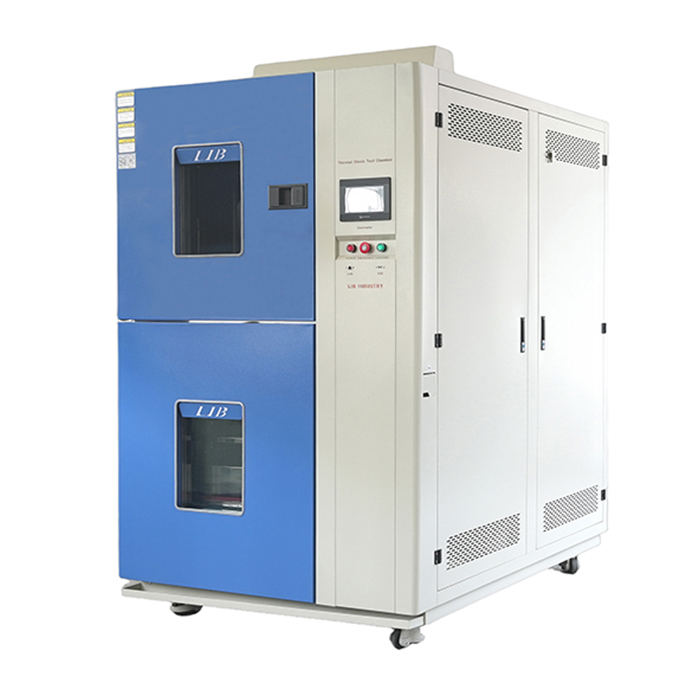
1. Thermal load determines chamber capacity: Physical volume alone does not indicate whether an Air To Air Thermal Shock Chamber can recover within the 5-to-15-minute windows required by standards such as MIL-STD-883 or IEC 60068-2-14.
2. Total test mass includes fixturing: The mass and specific heat capacity of the DUT, transfer basket, shelves, and fixtures should all be included.
3. Thermal conductivity affects recovery behavior: Copper and aluminum transfer heat rapidly, while low-conductivity materials such as FR4 release or absorb heat more slowly.
4. Airflow is as important as heating and cooling power: Strong refrigeration capacity provides limited benefit if airflow cannot penetrate dense sample arrangements.
5. Facility infrastructure affects available capacity: High-capacity Air To Air Thermal Shock Chamber systems may require high-amperage electrical service, water cooling, or auxiliary LN2 cooling.
In environmental testing, thermal mass describes a sample's ability to absorb, store, and release thermal energy. It depends primarily on the object's mass and specific heat capacity.
When evaluating an Air To Air Thermal Shock Chamber, engineers should consider thermal mass because it determines how much additional load the sample places on the chamber during rapid hot-to-cold or cold-to-hot transfers.
A heavy steel casting behaves very differently from a lightweight plastic enclosure, even if both occupy a similar amount of physical space.
A densely packed electronics assembly containing metal components or potting material can act as a significant thermal sink. When it is moved from a 150°C hot zone into a -65°C cold zone, the Air To Air Thermal Shock Chamber must remove not only heat from the chamber air but also the thermal energy stored inside the DUT.
Specific heat capacity determines how much energy a material stores, while thermal conductivity determines how quickly that energy moves between the sample and the surrounding air.
Highly conductive materials such as copper transfer heat quickly. When moved into the cold zone of an Air To Air Thermal Shock Chamber, they can create a sharp and immediate refrigeration load.
Materials with lower thermal conductivity transfer heat more slowly. In these cases, the chamber air may recover relatively quickly while the center of the product remains far from the target temperature.
| Material | Specific Heat Capacity (J/kg·K) | Thermal Conductivity (W/m·K) | Impact on Chamber Recovery |
|---|---|---|---|
| Aluminum | 897 | 237 | Rapid heat transfer can create immediate refrigeration load spikes. |
| Copper | 385 | 401 | Very rapid heat transfer requires high instantaneous cooling capacity. |
| Steel (Carbon) | 490 | 50 | Produces a more sustained thermal load during recovery. |
| FR4 (PCB Material) | 1300 | 0.25 | Transfers heat slowly and can delay product core-temperature recovery. |
Understanding these differences helps engineers predict how an Air To Air Thermal Shock Chamber will respond when a specific DUT is transferred between temperature zones.
An assembly containing large quantities of copper may impose an immediate peak load on the refrigeration system. An assembly dominated by FR4, insulation, or potting compounds may instead require a longer soak period before its internal temperature reaches the required value.
A high thermal mass sample acts as a heat sink when entering the hot zone and as a heat source when entering the cold zone.If the Air To Air Thermal Shock Chamber does not have sufficient zone capacity, the incoming sample can drive the chamber temperature away from its setpoint for an extended period. Consider a 50 kg EV battery module transferred into a cold zone. The battery continues releasing stored heat into the surrounding air. The chamber refrigeration system must remove this energy quickly enough to return the test zone to the specified temperature. If cooling capacity is insufficient, the air temperature may remain significantly above the required setpoint for 10 or 15 minutes. This changes the intended thermal shock profile.
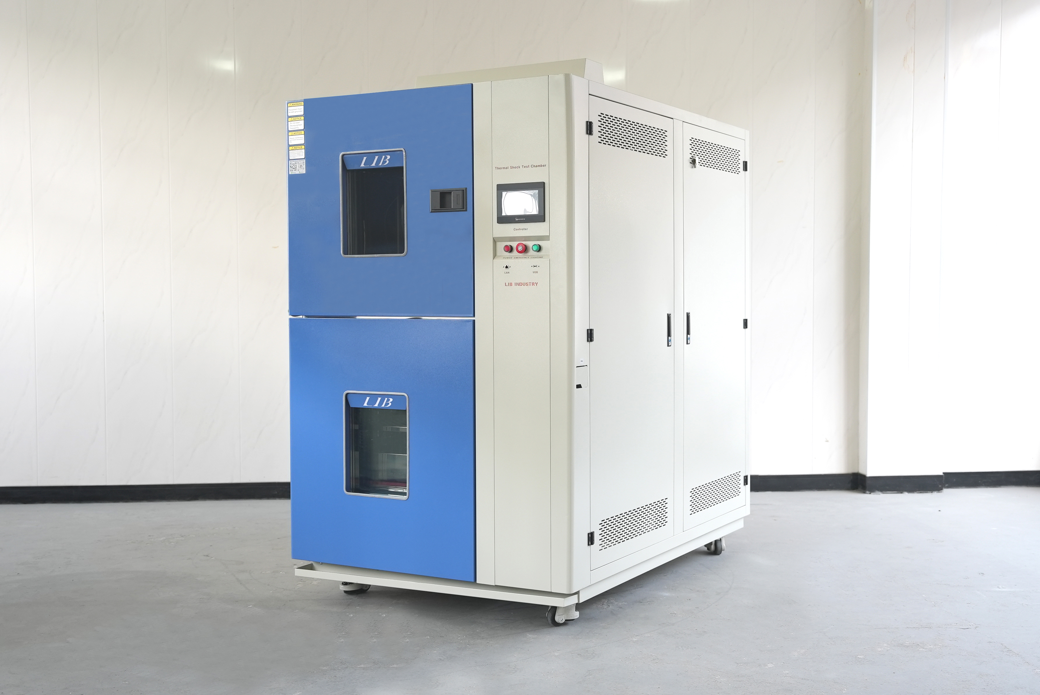
LIB Industry's air-to-air thermal shock chamber achieves a temperature recovery time of within 5 minutes, enabling rapid temperature stabilization. This performance ensures that, within the 5-to-15‑minute window required by standards such as MIL‑STD‑883 or IEC 60068‑2‑14, the chamber quickly returns the test zone to the setpoint. This preserves the true thermal shock effect (rather than degenerating into slow temperature cycling) and effectively meets the stringent requirements of product qualification testing.
Model | TS-162 | TS-340 | TS-500 | TS-1000 | |
Internal Dimensions (mm) | 300*300*250 | 450*450*360 | 650*650*500 | 850*850*700 | |
Overall Dimension (mm) | 1560*870*1545 | 1710*1020*1845 | 1910*1220*2265 | 2110*1420*2665 | |
Interior Volume (mm) | 22L | 72L | 211L | 505L | |
Loading Capacity | 20kg | 30kg | 50kg | 60kg | |
Pre-heat Room | Upper limit Temperature | +220℃ | |||
Heating Time | Ambient ~ + 200℃, within 30 minutes | ||||
Pre-cool Room | Lower limit Temperature | -75℃ | |||
Cooling time | Ambient ~ -70℃, within 30 minutes | ||||
Test Room | High Temperature Exposure Range | Ambient +20 ~ +200°C | |||
Low temperature Exposure Range | –65 ~ -5°C | ||||
Temperature Fluctuation | ≤±0.5℃ | ||||
Temperature Deviation | ≤±3 ℃ | ||||
Temperature Recovery Time | Within 5 minutes | ||||
Cooling System | Mechanical compression refrigeration system | ||||
Refrigerating Unit | French TECUMSEH compressor | ||||
Controller | Programmable color LCD touch screen controller Ethernet connection, PC Link | ||||
Safety Device | Over-temperature protection, Over-current protection; Refrigerant high-pressure protection; Earth leakage protection | ||||
Exterior Material | Steel Plate with protective coating | ||||
Interior Material | SUS304 stainless steel | ||||
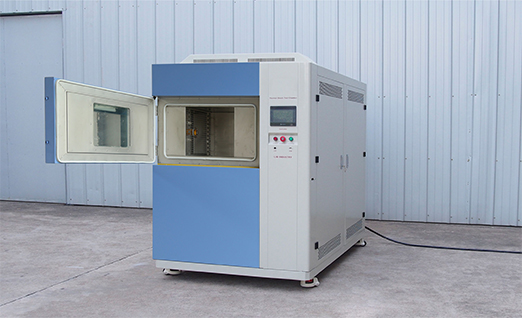
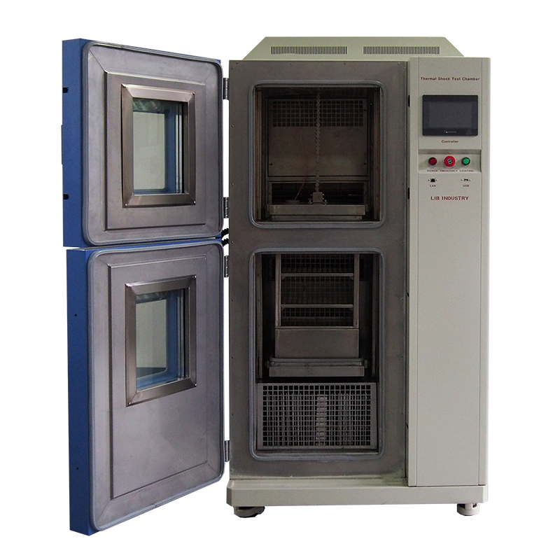
LIB Industry's two zone temperature shock tester typically uses a motorized basket or elevator to move the DUT between independently conditioned hot and cold zones. Because both zones are already at their target temperatures before transfer, this design can provide a rapid temperature change for the sample. For high thermal mass testing, the preconditioned hot and cold zones of an Air To Air Thermal Shock Chamber help provide the initial thermal reserve needed to absorb the incoming load. However, heavy samples introduce mechanical limitations as well as thermal ones.
The transfer mechanism must carry:
The DUT
The transfer basket
Mounting fixtures
Sensor wiring
Supporting hardware
For heavy battery modules or dense castings, engineers should verify the maximum load capacity of the Air To Air Thermal Shock Chamber basket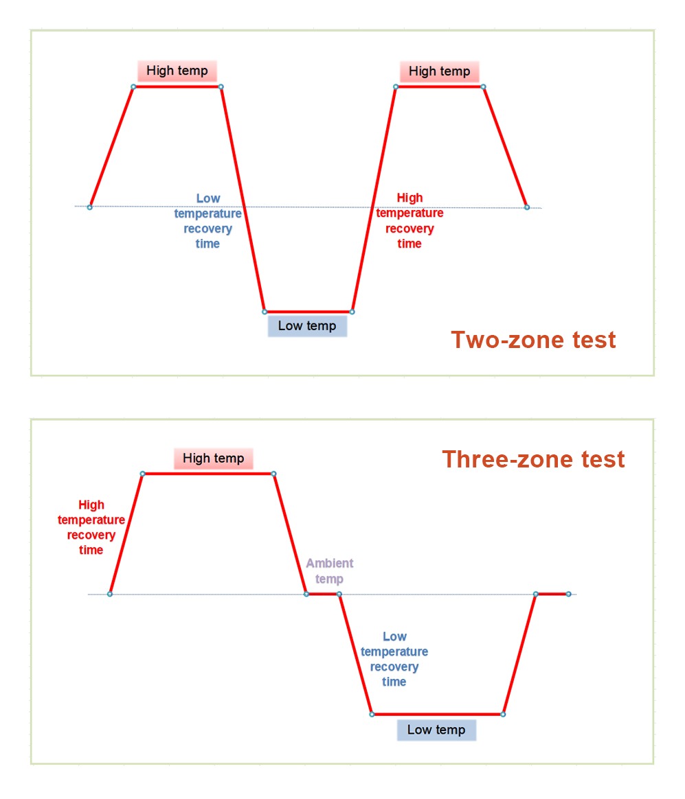 and transfer mechanism. Exceeding the mechanical load limit can cause poor transfer performance or damage to the system even if thermal capacity is adequate.
Some thermal shock systems keep the DUT stationary and switch conditioned hot and cold air into a single test space. This configuration eliminates the need to physically move a heavy sample. When evaluating a rapid transfer thermal chamber, engineers should compare the advantages and limitations of moving-basket and stationary-airflow designs.
Moving-basket Air To Air Thermal Shock Chamber systems can provide direct transfer between preconditioned zones but impose mechanical stress on the DUT. Stationary systems eliminate physical transfer but require very high airflow to purge the test space and establish the new temperature quickly.
Important evaluation points include:
Determine whether the DUT can tolerate physical transfer.
Calculate the combined mass of the DUT, basket, and fixtures.
Verify whether the airflow system can meet the required recovery time.
Compare maintenance requirements between mechanical transfer and damper-based systems.
| Item |
|
3-Zone Chamber (3TS Series) |
|---|---|---|
| Zone Structure | Hot zone + Cold zone (2 independent zones) | Hot zone + Ambient zone + Cold zone (3 zones) |
| Test Method | Specimen switches directly between hot and cold zones | Can select 2-zone or 3-zone shock; ambient zone allows a dwell period as a buffer |
| Models | TS-162 / TS-340 / TS-500 / TS-1000 | 3TS-100 / 3TS-210 / 3TS-300 / 3TS-500 |
| Interior Volume | 22L–505L | 100L–500L |
| Loading Capacity | 20–60kg | 10–35kg |
| High Temp Upper Limit | +220°C | +220°C (same) |
| Low Temp Lower Limit | -75°C | -70 to -75°C (similar) |
| Temp Fluctuation/Deviation | ±0.5°C / ±3°C | ±0.5°C / ±3°C (same) |
| Transfer Time | ≤3 seconds | Not specified |
| Controller Program Capacity | Not specified | 120 patterns, 9999 cycles |
| Warranty | 36 months + lifetime follow-up | 1 year free parts maintenance (standard) |
| Key Features | Defrost system, cable hole (live testing), movable shelving | Switchable 2-zone/3-zone modes, buffer zone closer to real-world conditions |
The required thermal load can be estimated using:Mass (kg) × Specific Heat (J/kg·K) × Temperature Change (ΔT) ÷ Target Recovery Time (seconds). This provides an engineering basis for estimating the heating or cooling capacity required from the Air To Air Thermal Shock Chamber.Calculations should normally use the worst-case transition. In many applications, transferring a hot high-mass sample into the cold zone creates the greatest refrigeration demand.
The calculation should not include only the DUT.
Engineers should also include:
① Transfer basket
② Shelves
③ Test fixtures
④ Mounting hardware
⑤ Product carriers
A heavy stainless-steel basket can contribute substantial thermal mass and therefore increase the required Air To Air Thermal Shock Chamber capacity.
Some DUTs contain materials that introduce additional thermal effects. Batteries, phase-change materials, and other assemblies may absorb or release latent heat during internal phase transitions.This energy cannot always be represented accurately using only a simple sensible heat calculation.Powered electronics can also create a continuous heat load.
For example, if an active DUT generates 500 W of internal heat while operating in the cold zone, the Air To Air Thermal Shock Chamber refrigeration system must remove this continuous heat in addition to the thermal energy transferred from the hot zone.
A passive metal casting gradually exchanges stored thermal energy with the chamber.
An active electronic assembly may simultaneously:
Release stored thermal energy
Generate electrical heat
Restrict airflow
Create localized hot spots
For active devices, LIB Industry recommends providing operating power dissipation data when evaluating Air To Air Thermal Shock Chamber capacity. This gives the manufacturer a more realistic basis for estimating temperature recovery performance.
High refrigeration capacity alone does not guarantee rapid recovery. Air must move efficiently around the DUT to transfer heat between the product and the conditioned environment. High-velocity airflow helps remove the boundary layer of air surrounding high thermal mass samples. If airflow is weak, even a powerful Air To Air Thermal Shock Chamber refrigeration system may struggle to exchange heat with the DUT efficiently. Dense sample arrangements can also create airflow shadowing. Outer surfaces may reach the target temperature much faster than internal or blocked areas.
For this reason, Air To Air Thermal Shock Chamber design should consider:
Fan capacity
Air velocity
Baffle design
Sample spacing
Basket openness
DUT orientation
Perforated baskets and sufficient clearance around the product can improve heat transfer and reduce recovery time.
LIB Industry's air circulation system features forward and reverse airflow capability, ensuring efficient air circulation through optimized fan capacity, air velocity, baffle design, sample spacing, and basket openness. For high-thermal-mass samples, powerful refrigeration alone cannot guarantee rapid recovery; sufficient and well-distributed airflow effectively removes the still air layer around the product, reduces airflow blockage caused by tightly packed samples, and thus improves heat exchange between the sample and the conditioned environment, significantly shortening recovery time.
| LIB popular Temperature Humidity Chambers | |||
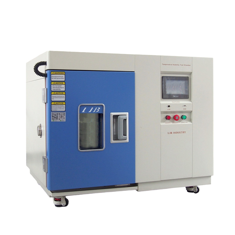
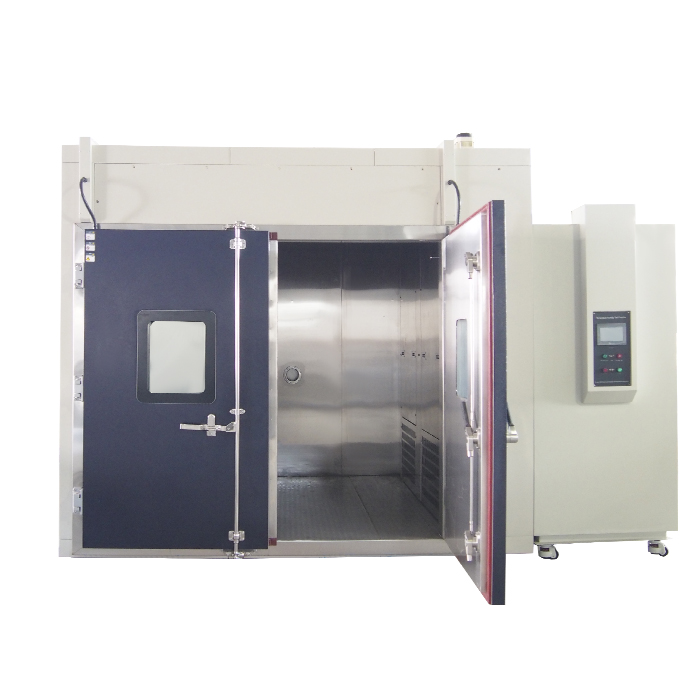
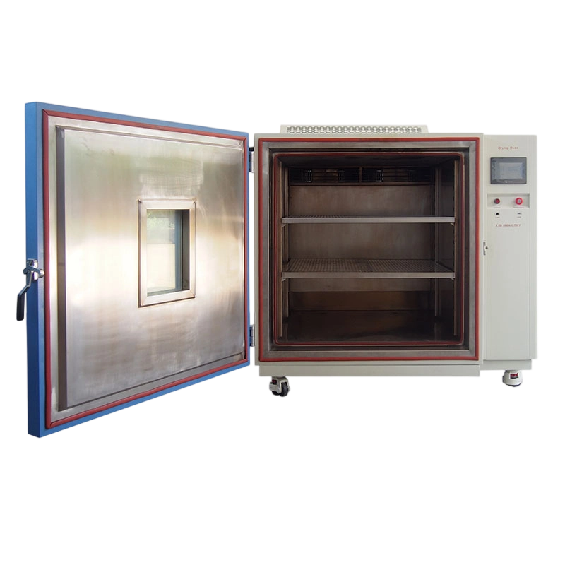
Standing temperature humidity chamber Precise climate simulation, Reliable long-term stability testing |
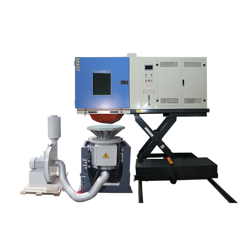
Combined Climate and Vibration Chamber Simulate temperature, humidity, and vibration stresses in one test |
Small temperature humidity chamber Compact footprint design, High-accuracy environmental control |
Walk-In temperature humidity chamber Large-capacity testing space, Ideal for oversized products |
Industrial High-Temperature Vacuum Drying Oven Uniform heat distribution, Efficient material drying |
Extreme thermal stress simulation, Fast failure detection capability |
Ultra-low temperature performance, Reliable cold resistance evaluation |
ICH-compliant stability testing, Precise temperature and humidity control |
Repeated transfers between extreme temperatures can introduce moisture into the cold zone. Over multiple cycles, this moisture may freeze on the evaporator coils. Frost acts as thermal insulation and can also restrict airflow. Both effects reduce Air To Air Thermal Shock Chamber cooling performance.
As frost accumulates:
Recovery time increases
Airflow decreases
Compressor load rises
Test consistency may decline
For long-duration thermal shock testing, chambers may therefore use automated defrost cycles. Dry-air purge or nitrogen purge systems can also reduce the amount of moisture entering the test space.Lower moisture levels help the Air To Air Thermal Shock Chamber maintain stable cooling performance across repeated cycles.
LIB Industry uses an automated defrost cycle to handle frost buildup in the cold zone. When samples move between hot and cold zones, moisture can enter and freeze on the cooling coils. This frost reduces cooling power and blocks airflow. By running defrost cycles regularly, LIB chambers keep cooling performance stable even during long tests with many cycles. This prevents recovery times from getting longer and keeps test results consistent.
Selecting the right Air To Air Thermal Shock Chamber for high thermal mass samples requires more than confirming that the product physically fits inside the test basket. The chamber must have sufficient heating, cooling, airflow, and mechanical transfer capacity to handle the complete thermal load while meeting the required temperature recovery time.
Before selecting an Air To Air Thermal Shock Chamber:
Calculate the thermal mass of the worst-case DUT, including baskets, fixtures, and shelving.
Provide the sample materials and specific heat information where available.
Define the required hot and cold temperatures.
Confirm the maximum allowable recovery time.
Include active heat dissipation for powered DUTs.
Evaluate basket weight limits and transfer mechanics.
Confirm facility electrical and cooling-water capacity.
Use product-temperature thermocouples to verify actual soak conditions.
For heavy batteries, dense electronic assemblies, metal components, and other high thermal mass products, LIB Industry can evaluate these factors when configuring an Air To Air Thermal Shock Chamber for the required testing profile.
A two-zone system transfers the DUT directly between dedicated hot and cold environments. A three-zone system introduces an intermediate ambient zone between the temperature extremes. The appropriate configuration depends on the required test method.
Higher mass means more thermal energy must be removed or added during each transfer. If the Air To Air Thermal Shock Chamber has insufficient heating or cooling capacity, the zone will take longer to return to the required temperature.
High-conductivity materials transfer heat rapidly and can create a sharp initial load on the Air To Air Thermal Shock Chamber. Low-conductivity materials release or absorb heat more slowly, which can significantly delay the core temperature of the DUT.
It depends on both the mechanical load limit and thermal capacity. The basket must safely support the DUT and fixtures, while the Air To Air Thermal Shock Chamber must also have enough heating or cooling capacity to meet the required recovery time.
Specific heat indicates how much thermal energy a material stores. Two products with the same mass can impose different loads on the Air To Air Thermal Shock Chamber if they are made from materials with different specific heat capacities.
LN2 boost may be useful when mechanical cascade refrigeration alone cannot recover the cold zone within the required time. Whether it is necessary depends on DUT mass, material properties, temperature extremes, and the applicable testing standard.
Dry-air or nitrogen purge systems can reduce moisture inside the Air To Air Thermal Shock Chamber. Automated defrost cycles can also remove frost that develops on evaporator coils during repeated testing.
If you're in the market for a thermal shock test chamber, whether it's a 2-Zone Thermal Shock Test Chamber, a 3-Zone Thermal Shock Test Chamber, or an Air To Liquid Thermal Shock Chamber for high thermal mass samples like EV battery modules or dense PCB assemblies, don't hesitate to reach out. We're ready to discuss your DUT size, weight, material composition, required temperature range, recovery-time requirements, and applicable test standards, and help you find the right thermal shock solution for your laboratory.
LIB Industry Technical Team (info@lib-industry.com), Technical information, testing methods, product specifications, and application guidance for thermal shock and environmental test equipment.