Views: 0 Author: Site Editor Publish Time: 2026-05-22 Origin: Site


Selecting an environmental test chamber is a high-stakes, structural decision. It directly impacts product reliability,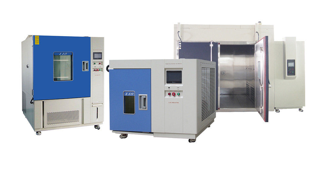 regulatory compliance, and warranty structuring for the next decade. Buyers often mistakenly focus solely on internal volume and basic temperature ranges. They ignore the complex thermodynamics, facility constraints, and safety integrations required for reliable testing. This oversight frequently leads to stalled pull-down rates, inaccurate test results, and hardware failure.
Recently, a Swedish electronics company shared positive feedback after operating a LIB Environmental Test Chamber in their laboratory. The customer commented, “The chamber is operating well. Since it hasn't been running continuously, the overall wear should be minimal. Thank you for the service and maintenance guide.” The customer also asked whether LIB has local service partners in Sweden to provide additional support. This feedback reflects not only the chamber's operational reliability, but also LIB Industry's commitment to long-term technical support and customer service.
This guide breaks down the engineering variables, physical limitations, and facility prerequisites you must evaluate. You will learn how to calculate dynamic live loads, assess complex transition mechanics, and prepare your laboratory infrastructure. By mastering these physical and thermodynamic realities, you can confidently evaluate, shortlist, and procure the correct testing equipment for your laboratory.
Volumetric Airflow: Always maintain a minimum 1:3 product-to-workspace volume ratio to prevent air stagnation and thermal dead zones.
Dynamic Heat Mitigation: Factoring in "live loads" (heat actively generated by the product) is critical; high live loads severely throttle a chamber’s pull-down rate and require upgraded refrigeration.
Refrigeration Realities: Single-stage mechanical compressors reliably reach -34°C to -40°C, while deeper sub-zero requirements demand dual-stage cascade systems or consumable refrigerants (LN2/CO2).
Infrastructure Preparation: High-performance floor models universally require three-phase power, 18–36 inches of ventilation clearance, and strict ambient room temperature controls (~23°C).
Before you evaluate hardware specifications, you must explicitly define your regulatory standards. You also need to outline the physical stresses the machine must replicate.
Every industry follows specific testing protocols. You must identify the exact guidelines governing your product. Aerospace engineers typically design tests around MIL-STD requirements to simulate extreme atmospheric conditions. Electronics manufacturers often rely on IEC or JEDEC standards to ensure circuit board reliability. Pharmaceutical laboratories follow strict FDA stability guidelines to verify drug shelf life. You should compile a comprehensive list of these mandatory standards before you approach any manufacturer. It prevents you from under-specifying your testing parameters.
Different materials respond uniquely to thermal and humidity stress. When sourcing an Environmental Test chamber For Composites, you must prioritize systems capable of rigorous temperature-humidity cycling. Composite materials often hide internal weaknesses. Rapid thermal cycling accurately induces moisture absorption, matrix degradation, and structural delamination. You can then observe these failures under controlled thermal stress. Standard chambers might lack the precise humidity control needed to expose these composite vulnerabilities.
You must distinguish between steady-state testing and rapid thermal cycling. Steady-state testing involves long-term exposure at fixed parameters. It tests how a product endures constant heat or moisture over months. Conversely, rapid thermal cycling subjects products to sudden, drastic shifts. Methodologies like HALT (Highly Accelerated Life Test) or HASS (Highly Accelerated Stress Screen) require dramatically higher transition rates. To achieve these rapid shifts, manufacturers build HALT/HASS chambers using reinforced construction and oversized airflow systems.
Chamber sizing is an exercise in airflow dynamics and thermodynamics. It involves much more than measuring physical geometry.
A test object should never occupy more than one-third of the internal volume. Overcrowding is a common mistake. It blocks forced-air convection inside the workspace. When you block airflow, you create thermal dead zones. The air temperature sensor might read the target temperature, but the product temperature severely lags behind. Maintaining this 1:3 ratio guarantees adequate air circulation, ensuring accurate, repeatable test results.
Heavy, dense products absorb significantly more thermal energy. High product density increases the time required for the actual component to reach target temperatures. If you test heavy metallic blocks, the air cools much faster than the metal itself. To overcome this thermal lag, the system needs massive airflow. You often need air velocities up to 500 ft/min to force heat transfer.
If the device under test (DUT) remains powered on, it generates heat. We call this active thermal generation a "live load." You must subtract this live load from the chamber’s total cooling capacity. Failure to account for active heat generation causes severe performance issues. It results in stalled pull-down rates. The system may entirely fail to reach extreme low temperatures.
Steps to Calculate Sizing and Loads
1. Measure the DUT: Determine the precise physical dimensions of the largest item you plan to test.
2. Apply the Ratio: Multiply the DUT volume by three to find your absolute minimum internal workspace requirement.
3. Calculate Live Load Watts: Determine the maximum wattage your powered device dissipates during testing.
4. Consult the Cooling Curve: Compare your live load wattage against the manufacturer's cooling performance curve at your lowest required temperature.
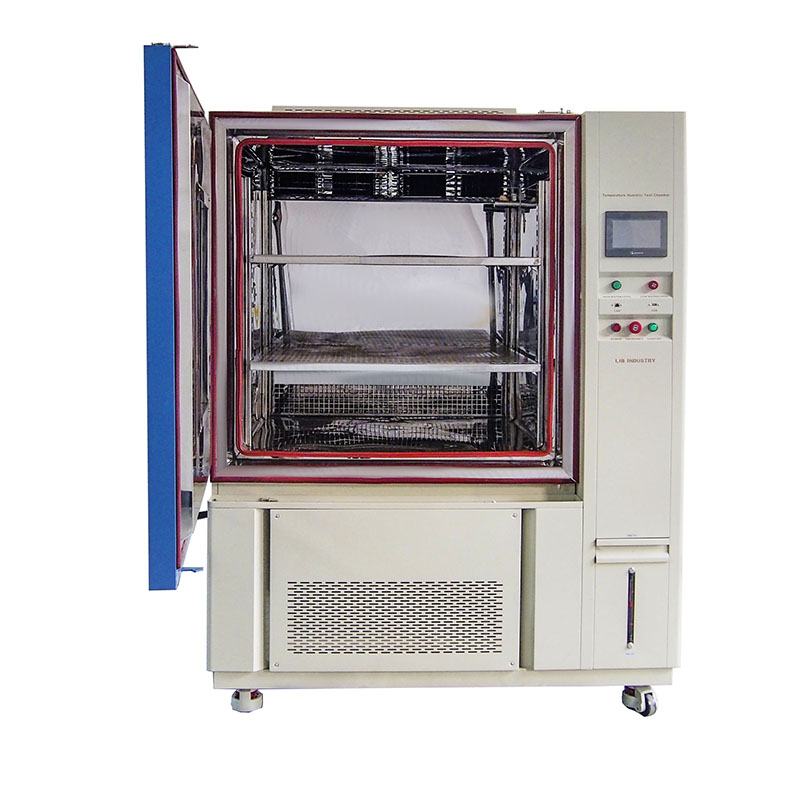 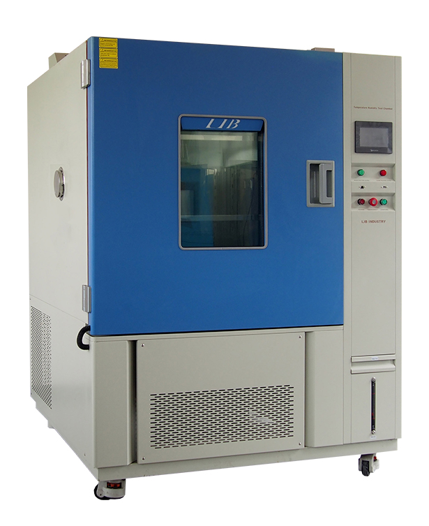 | |||||
Temperature range | -20℃ ~+150 ℃ | ||||
Low type | A: -40℃ B:-70℃ C -86℃ | ||||
Humidity Range | 20%-98%RH | ||||
Temperature deviation | ± 2.0 ℃ | ||||
Heating rate | 3 ℃ / min | ||||
Cooling rate | 1 ℃ / min | ||||
Controller | Programmable color LCD touch screen controller, Multi-language interface, Ethernet , USB | ||||
Refrigerant | R404A, R23 | ||||
Exterior material | Steel Plate with protective coating | ||||
Interior material | SUS304 stainless steel | ||||
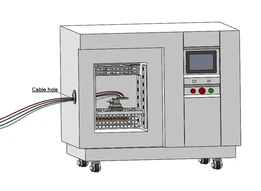
Standard configuration | 1 Cable hole (Φ 50) with plug; 2 shelves | ||||
Timing Function | 0.1~999.9 (S,M,H) settable | ||||
|
| 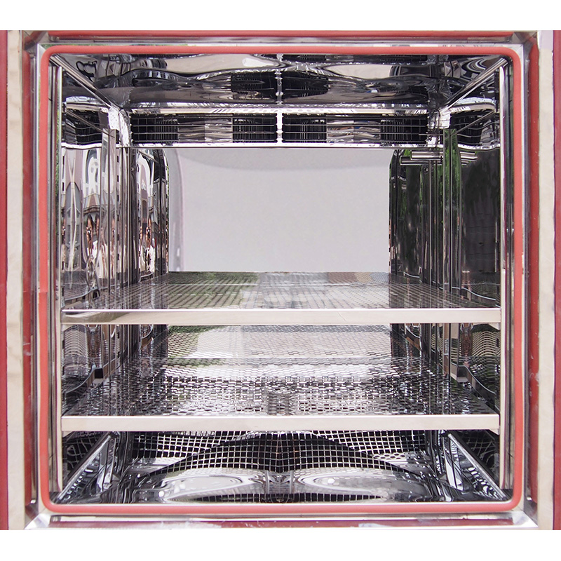 | 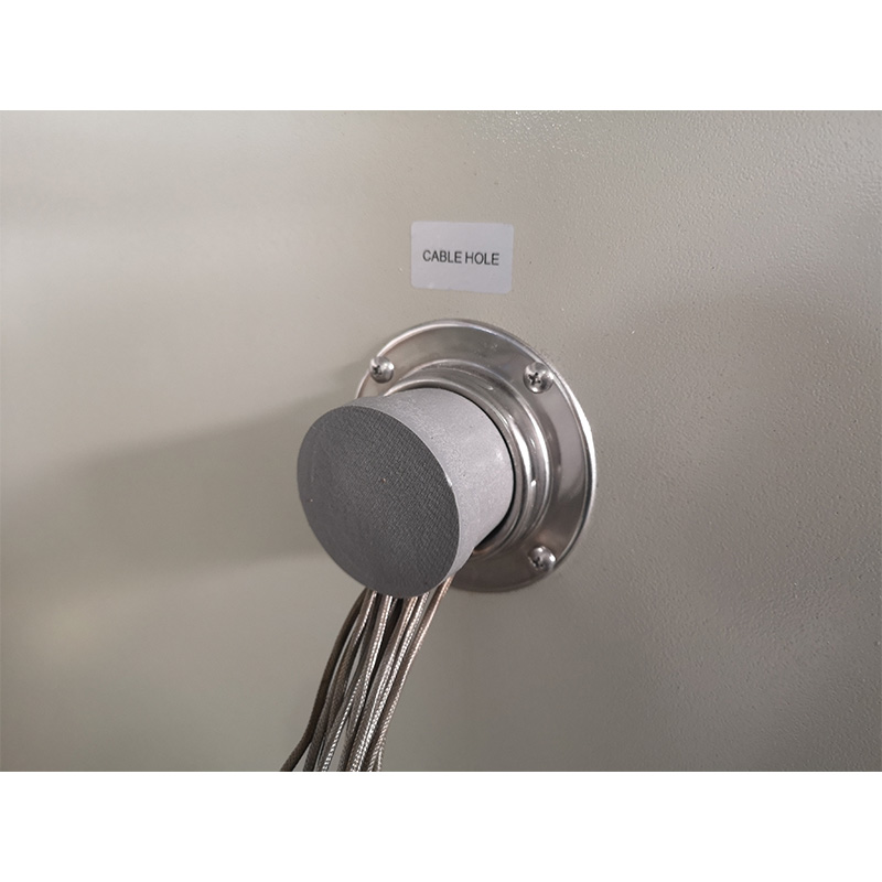 |
Touch screen controller | The compressor | Robust Anti-Corrosion Workroom | Integrated Power Access hole |
You must scrutinize the underlying hardware powering the environmental extremes. This prevents you from overestimating your lab's capabilities.
Manufacturers design refrigeration modules in distinct tiers based on target temperatures. Understanding these tiers helps you select the right mechanical setup.
Refrigeration Type | Optimal Temp Range | Best Use Case | Operational Considerations |
|---|---|---|---|
Single-Stage Compressor | Down to -40°C | Standard steady-state testing | Highly reliable, requires standard preventative maintenance. |
Cascade (Two-Stage) System | -70°C to -85°C | Deep-freeze electronic testing | Uses two interdependent circuits; requires dedicated three-phase power. |
Consumable Refrigerants | Down to -184°C | Ultra-low aerospace extremes | Uses LN2 or liquid CO2; requires strict outdoor exhaust plumbing to prevent lab asphyxiation. |
Standard machines are restricted by a 5°C dew point. This limit prevents the internal evaporator coils from frosting over. When coils freeze, airflow stops, and temperature control fails. If your testing requires deep sub-freezing humidity, standard systems will not work. You must add a desiccant dry-air purge system. This accessory actively strips moisture from the air, allowing you to achieve extremely low humidity levels without destroying the refrigeration coils.
Rapid temperature transitions cause violent air expansion and contraction. For example, moving from 10°C to 30°C per minute changes internal air pressure rapidly. Even a minor 0.25 psi differential can exert nearly 475 lbs of force against a standard door. Such force can blow open seals or warp structural hinges. You must ensure high-ramp units are equipped with calibrated pressure-relief vents to safely exhaust this expanding air.
 |  |  | |
|---|---|---|---|
 |  |  | |
| Name | Small temperature humidity chamber | Standing temperature humidity chamber | Walk-In temperature humidity chamber |
| Capacity | TH-50: 800x1050x950 mm TH-80: 900×1100×1000mm | Capacity: 100L; 225L; 500L; 800L; 1000L | >20m³ |
| Throughput | Ideal for small components, sensors, boards | Subassemblies or mid-volume batches | Bulk testing of items or vehicles as a whole |
| Energy Saving | Automatic Moisture Circulation in Humidity System
| Automatic Moisture Circulation in Humidity System
| Automatic Moisture Circulation in Humidity System
|
| Operational Cost | Lowest | Medium | Highest |
| Standards Coverage | Full IEC / ISO / ASTM compliance | ||
Long-term reliability hinges on manufacturing techniques. High-quality construction protects internal insulation and ensures thermal consistency.
You should reject riveted or poorly sealed internal joints. Test environments cycle between extreme heat and moisture. If a joint relies on rivets, moisture will eventually penetrate the seams. It seeps into the fiberglass or mineral wool insulation hidden within the walls. This causes silent thermal degradation and cabinet rusting. You should mandate continuously welded seams. Ideally, the manufacturer should use 304-grade stainless steel to eliminate any risk of moisture intrusion.
Cooling mechanisms reject massive amounts of heat into your laboratory. An air-cooled condenser exhausts roughly 12,000 Btu/h per compressor horsepower. If your facility HVAC cannot offset this heat, your room will quickly overheat. When the room overheats, the testing equipment fails to cool properly.
Condenser Comparison Chart
Cooling Method | Facility Requirements | Advantages | Disadvantages |
|---|---|---|---|
Air-Cooled | Robust room HVAC, clear ventilation space. | Easier installation, no plumbing required. | Dumps massive heat and noise into the lab space. |
Water-Cooled | Chilled water supply, floor drains, plumbing. | Keeps lab quiet and cool, highly efficient. | Complex installation, vulnerable to water scale/leaks. |
Standard builds rarely handle hazardous test objects safely. For hazardous tests, like lithium-ion battery cycling, you need specialized modifications. Batteries can undergo thermal runaway, leading to severe explosions. Your hardware must feature automated fire suppression systems and toxic gas exhaust ports. Furthermore, explosion-proof blast chains and reinforced door latches are essential to protect your lab personnel from catastrophic device failures.
The most frequent point of failure in deployment is a lack of facility infrastructure. Buyers often receive their equipment only to realize their lab cannot support it.
An Environmental Test chamber operates optimally in a stable, climate-controlled room. The ideal ambient temperature hovers around 23°C (70°F). High ambient lab temperatures severely overwork the internal condenser. This shortens the compressor lifespan and limits its low-end performance capabilities. Your facility HVAC must run constantly to maintain this strict baseline room temperature.
Before ordering, map the exact delivery route from the loading dock to the laboratory.
Delivery Path: Verify the crated unit can clear hallway widths, lab doorways, and freight elevator weight limits.
Ceiling Height: Ensure you have vertical clearance for exhaust ports or crane rigging if required.
Operating Clearance: Once installed, reserve 18 to 36 inches of rear and side clearance. This space is mandatory for maintenance access and proper heat dissipation.
Electrical requirements vary wildly based on size and capability. Small benchtop models typically run on standard 120V single-phase power. However, high-capacity floor models and dual-stage cascade configurations universally require dedicated three-phase facility power. Verify your building's electrical panel capacity. Supplying improper voltage will instantly damage sensitive control electronics and ruin heavy-duty compressors.
Procuring testing equipment represents a deep commitment to your laboratory's R&D integrity. Instead of shopping based solely on brochure temperature limits, you must build your criteria around thermodynamic realities. Assess your dynamic live loads and map out your facility's HVAC limitations. Define your material testing protocols strictly against industry guidelines. Finally, consolidate your footprint requirements, target transition rates, and safety prerequisites into a formalized Request for Proposal (RFP). This structured approach guarantees you acquire hardware capable of executing precise, repeatable testing for years to come.
A: Temperature fluctuation measures how stable the temperature remains at a single stationary point over time, usually varying by ±0.5°C. Uniformity measures the maximum temperature variance across the entire internal workspace at a given moment, typically staying within ≤2.0°C. Both metrics dictate overall accuracy.
A: The display reads the circulating air temperature, not the solid product temperature. Dense products have high thermal mass, creating a physical thermal lag. Achieving true product temperature requires sufficient airflow convection and adequate physical soak time.
A: With preventative maintenance, regular sensor calibration, and a stable ambient operating environment, a commercial-grade continuously welded unit typically operates reliably for well over 10 years. Routine cleaning of condenser coils is critical to reaching this lifespan.
Contact LIB Industry today to discuss your laboratory testing requirements and find the right environmental test chamber solution for your application.